A Low-Profile, Ergonomic Split Keyboard
Why "Low Tide"? It's a reference to the low profile form factor, as well as a nautical theme I've tried to weave through it:
from the choice of colours representing foamy waves to the clear bottom plates that let you peek at my handiwork!
This project marked a bit of a turning point in my journey as a maker. It was the first time I started a project knowing I didn't have the skills to finish it (the main obstacle was the programming). The leap of faith was well worth it, and it must have resulted in a huge step in self confidence since that element of "unknown but learnable" has been present and growing in each of the projects I've embarked on since then!
As of writing this, the Low Tide has been my main keyboard for about 4 months. Its firmware has gone through 8-10 updates adding new features to the point where I'm happy with it and have learnt to touch type at about 40wpm: far surpassing my previous speed on a typical QWERTY plank with my eyes locked onto my hands. Mission accomplished! It's played a crucial role in each of my projects since then, including dozens of hours of CAD and code, including this entire website!
The following section titles are clickable shortcuts if you're interested in a step in particular:
Presentation and Showcase
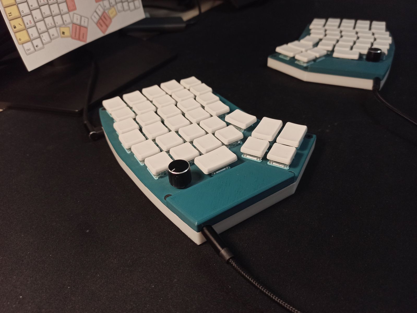
Form Factor
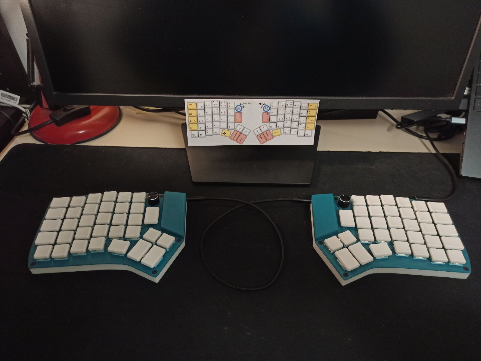
As you can tell from the pictures, this is a split keyboard with an ergonomic layout called the Redox designed by Mattia Dal Ben and slightly customised to fit my needs.
The keys are left intentionally blank, the thought was that it would force me to learn the layout. I still keep a slip of paper under my monitor for those characters I don't use as often but I can imagine not needing that soon.
By spacing both halves of the keyboard, the angle of the wrists becomes much more natural which goes a long way towards reducing the risk of carpal tunnel syndrome and other forms of wrist pain.
The unusual layout also means I can access all the keys without moving my hands unlike a regular keyboard which made learning to touch type much faster as well as increasing overall typing speed.
Features
Since the keyboard is running QMK, an Open Source keyboard firmware configured in C, each key is entirely customisable.
This allows for some really interesting functionalities that aren't found on most consumer keyboards:
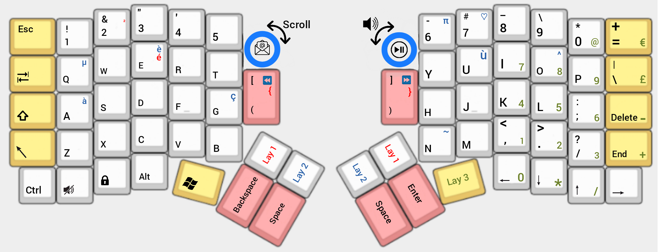
- Layers are a way of doubling, tripling, etc. the number of keys you have by changing all their functions based on which other key is being held or was last pressed. You can think of it like shift on steroids! I have 4 layers: a base qwerty layout, then Lay_1 to Lay_3 on which I have the accents I need for daily communication here in France and functions I wouldn't have been able to fit onto the 70 keys at my disposal. The picture on the right shows which characters are on which layers and how they can be accessed by the thumb clusters. I have a total of 44 extra characters and symbols on top of the standard 70 on my default layer. These include a full number pad, currency symbols and media functions.
- Macros are keys that execute small functions, such as typing out character strings. You could have a hardwired password manager with secret key combinations or set shortcuts to open certain applications and change settings. I just used a macro to map my email address to a key.
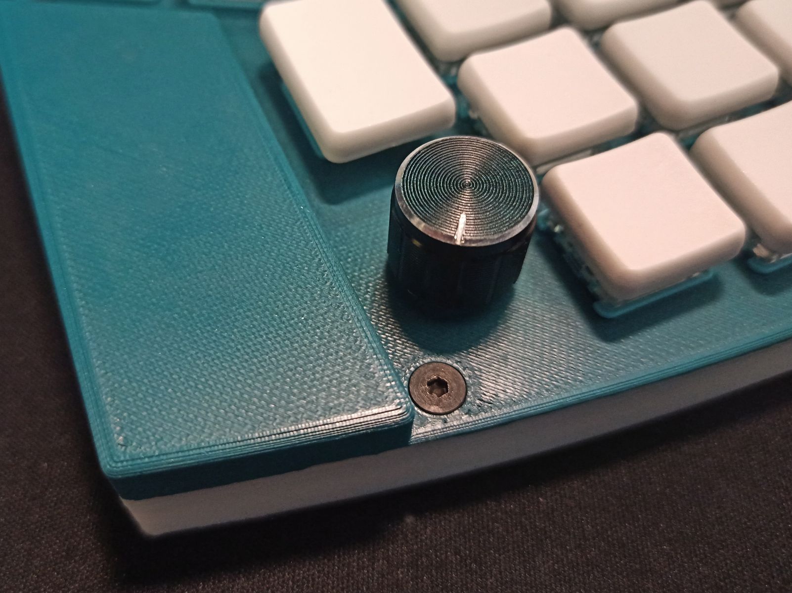
- Encoders are knobs that can serve as both a clickable key and rotary dial which can be set to control all sorts of menus/values.
Hover your cursor over a video to play it:
On the left is a demo of the left encoder serving an ALT+TAB function as well as typing out my email address.
On the right is a demo of the right encoder used for media control.
Design
Layout choice
Why the Redox layout?
I liked the look of the thumb clusters to take away some of the strain on the little fingers and make the most of all the thumbs' degrees of freedom.
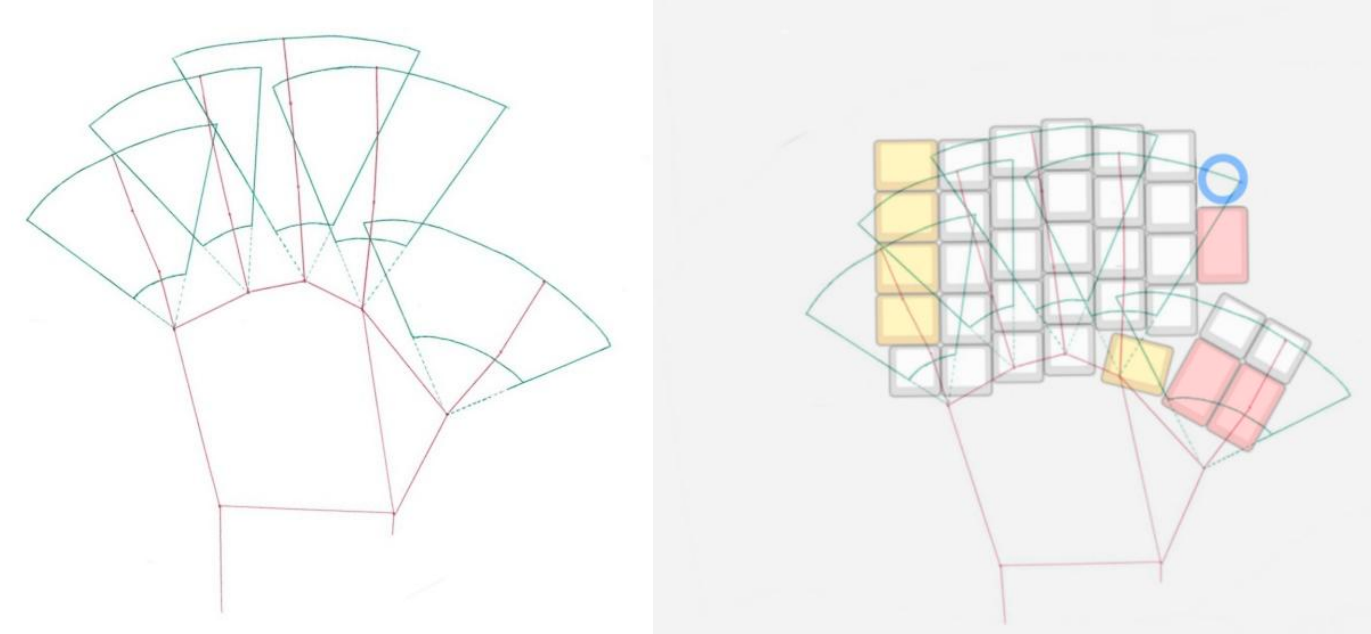
But the number one criteria was if or not I could reach all the keys without moving my hands.
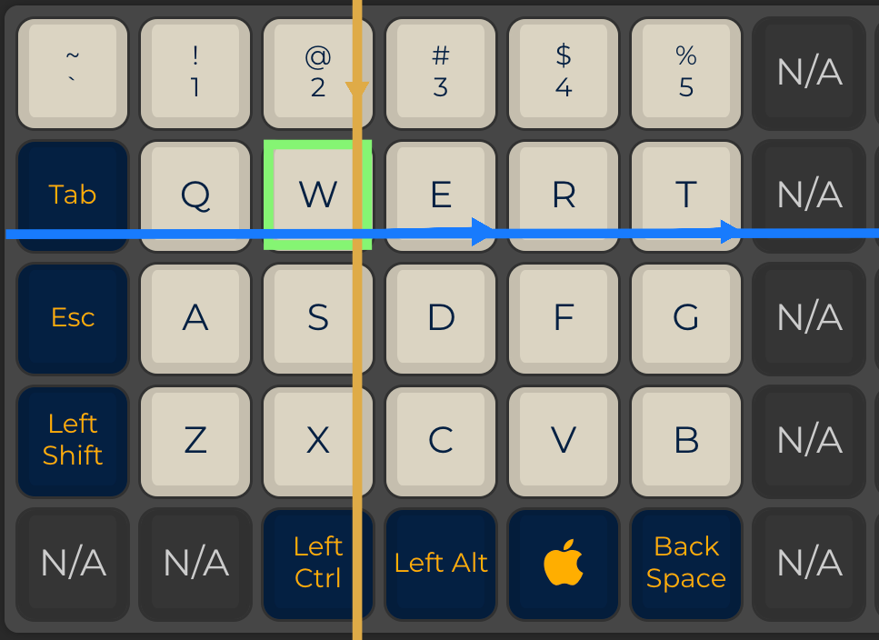
In order to determine whether or not this box was ticked I traced the resting position of my fingers in red and proceeded to add the limits of the areas each digit could reach in green.
It turns out the fit is pretty much perfect.
The few keys outside of the zone are still reachable although with less comfort. This isn't a problem since these keys don't see as much use in the first place.
Case Design
A quick search on any 3D model database will return plenty of existing Redox cases, but as it so often happens none of them quite fit my needs.
My version needed the following features:
My version needed the following features:
- Low profile form factor. This is less common in mechanical keyboards, and means a different footprint for the switches, finding space for the microcontrollers to sit on the same plane as the other components and less room to route cables.
- Clear panels on the underside to showcase the inner workings.
- Encoders in place of the switches above the index fingers to allow for more functionality for the size
- Clear panels on the underside to showcase the inner workings
- USB C ports instead of the Micro USB connectors on the Pro Micro
- Easy to disassemble so I can still get to the RESET pin for flashing new firmware versions

Build
Case Assembly
The parts were printed on a Prusa MK3 with no warping despite a large surface in contact with the print bed.
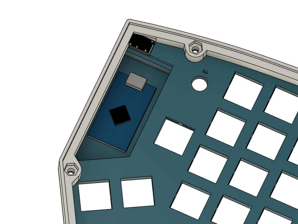
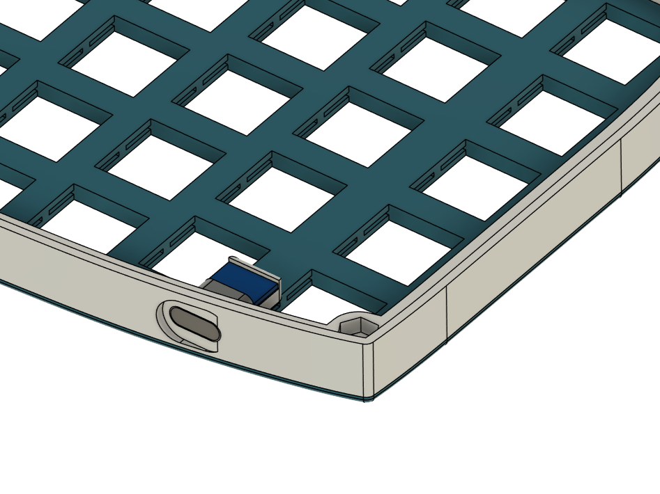
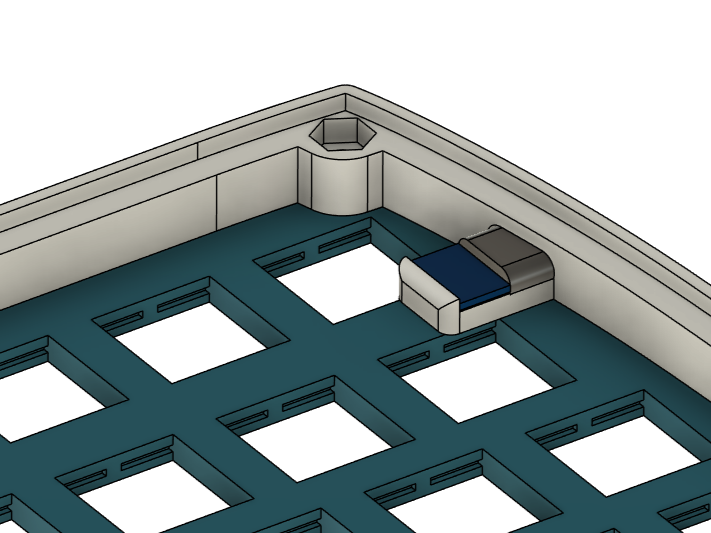
The inward sides of the top plate have recessed areas where the pro micros sit, alongside a standard 4pin TRRS 3.5mm jack connector which will support the I2C bus linking both halves.
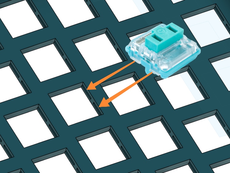
Each switch socket has dedicated slots for the clips on the side of the low profile Kailh Choc's body so it clips in nicely.
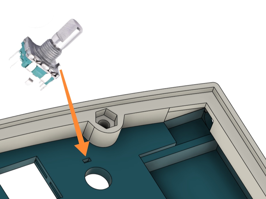
A hole is present next to the encoder holes that house a metal peg on the casing to prevent it from slipping under the torque later on.
The USB port sits in a separate piece to prevent unnecessary support material, it's then glued to the top plate.
The body also is assembled to the top plate, but with pockets for M3 nuts so countersunk bolts can clamp the assembly together.
Wiring: Matrix
The Pro Micro microcontrollers I'm using have a total of 18 usable GPIOs.
This is obviously not enough to wire each of the 35 keys/half to their own pin, let alone the connections for the I2C bus and encoders.
Instead we can use a matrix configuration, not unlike a battleships board we now only need connections for each of the columns and rows bringing the required pins so far to a much more manageable 12 per half.
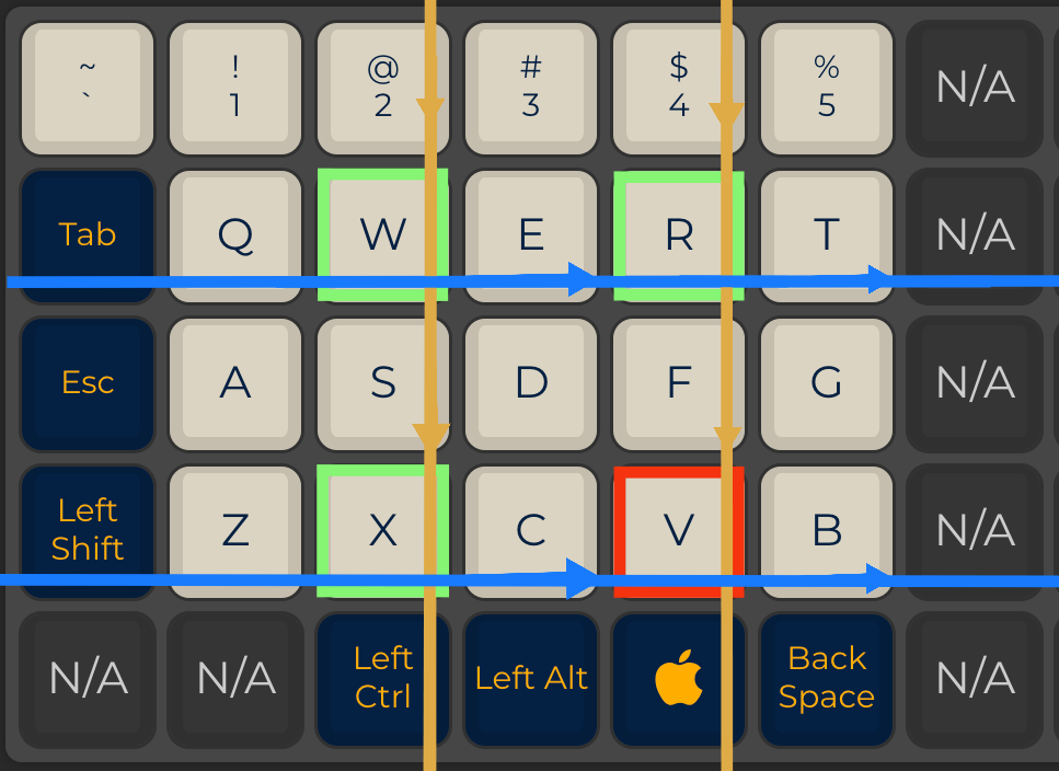
To read the pressed keys in the matrix we can simply pulse voltage across the columns one at a time and check if it appears on any of the rows.
If we spot a signal edge, we can print the assigned character right? Almost: there's one exception we need to look out for.
On the top picture to the right only one key is pressed and in turn only one key stroke is picked up, however if any 3 keys are pressed as in the bottom picture which share both a column and a row, we get a ghost stroke where the current has flowed back up the other way.
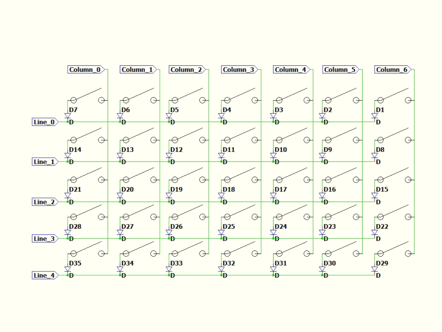
This can be resolved simply and cheaply with the use of diodes between any two switches on a given column as seen in the schematic below.
This forces the current to flow in one direction only and has the added benefit of making the circuit look more complicated than it is at a glance!
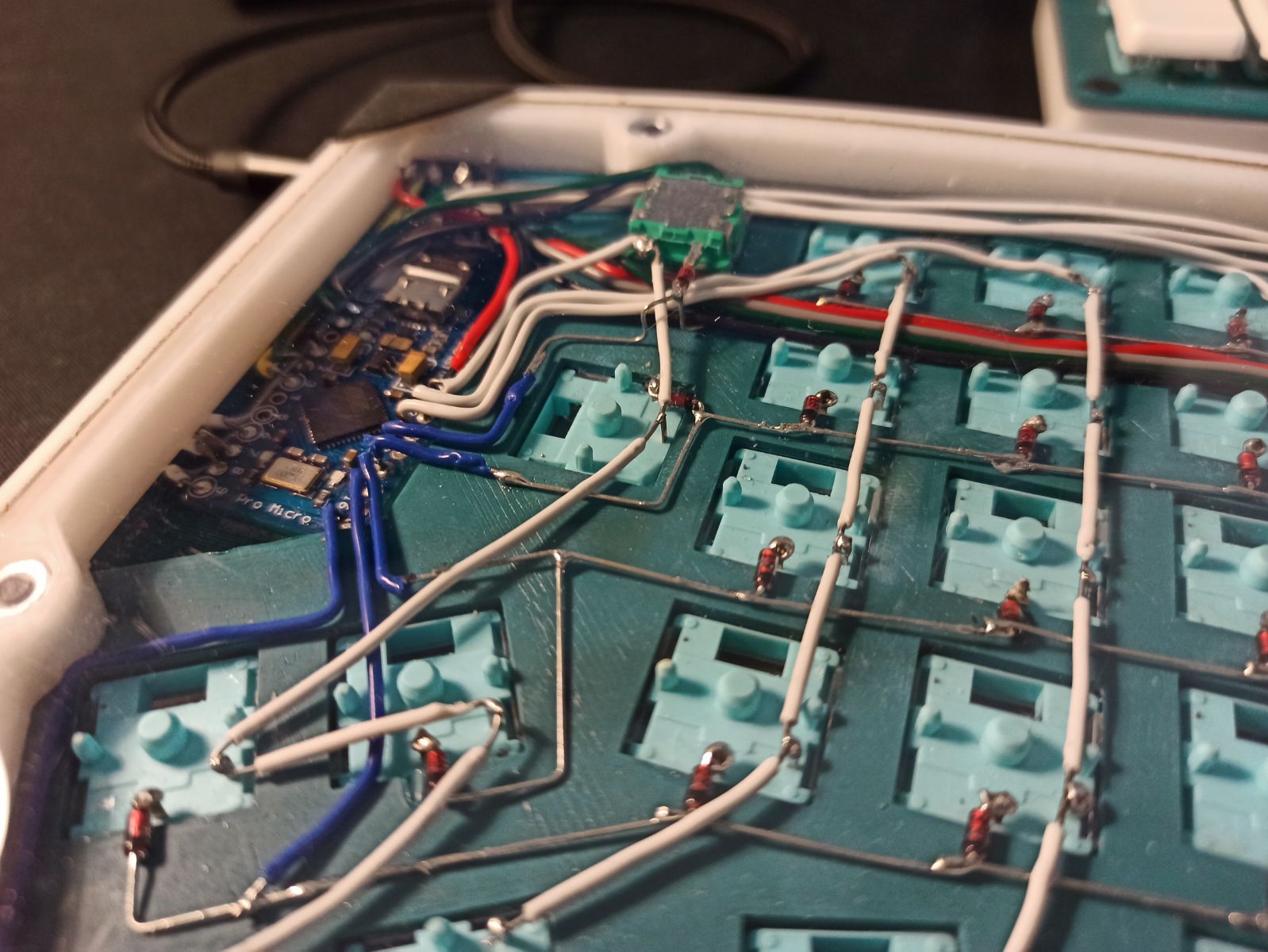
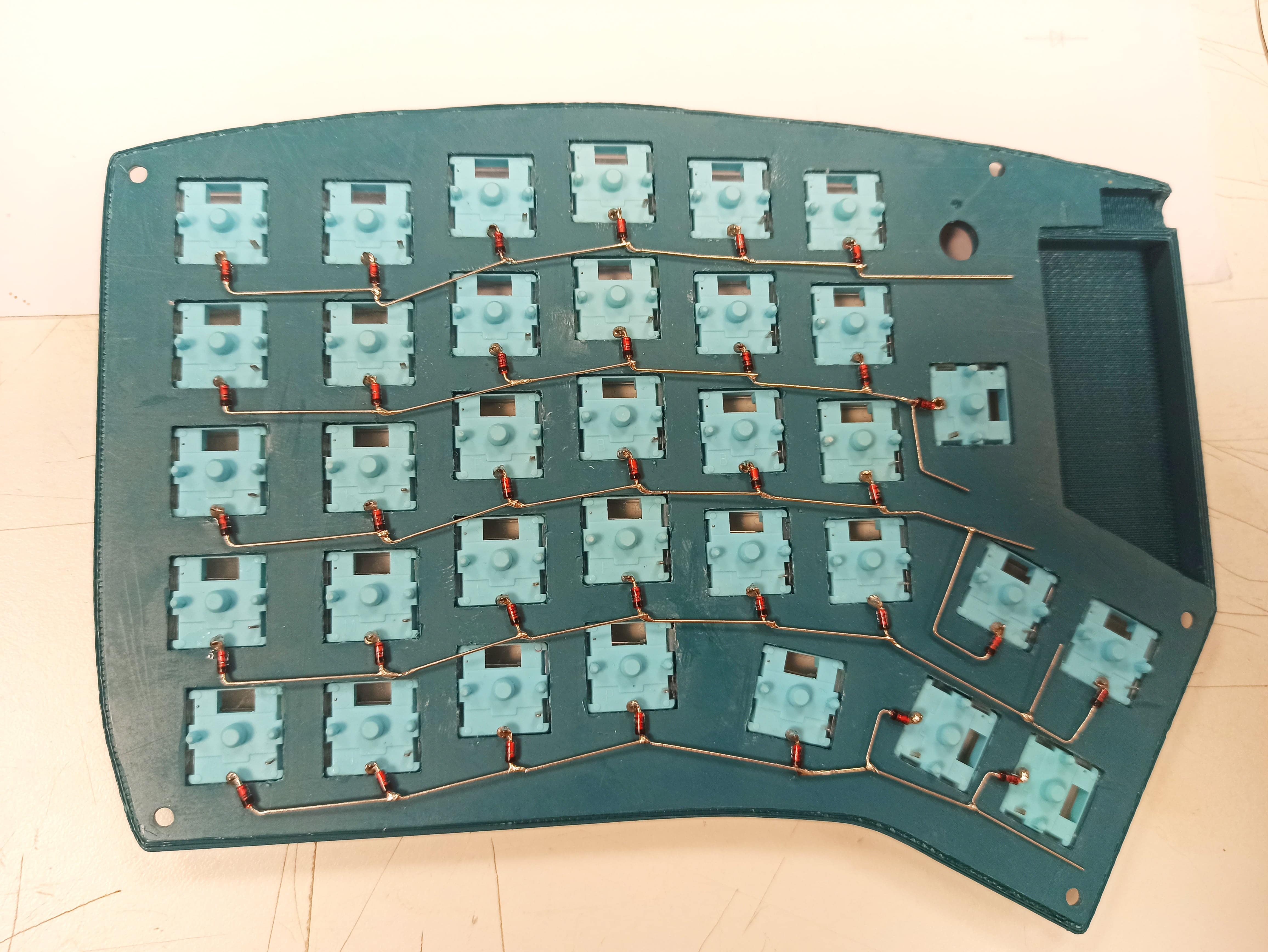
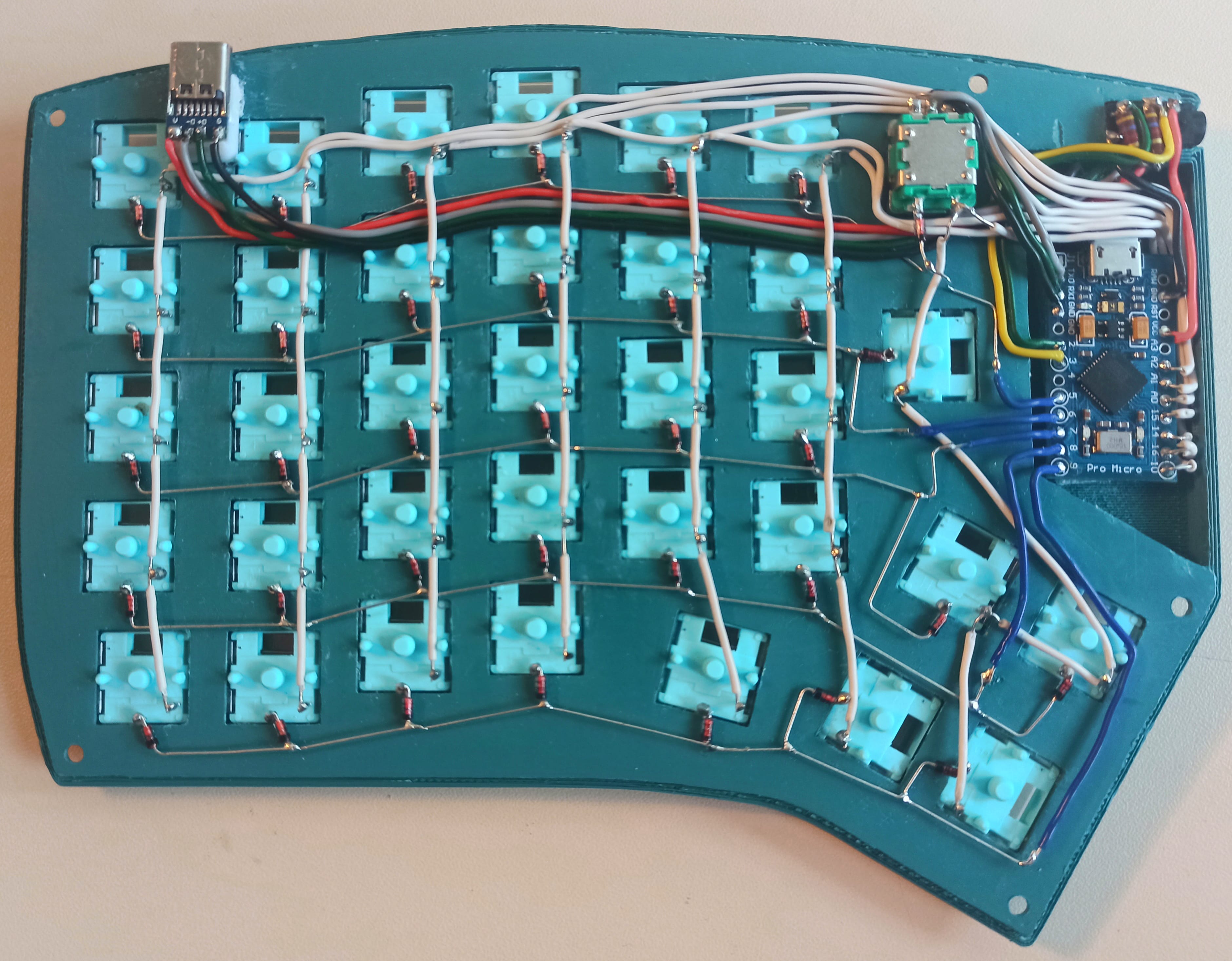
The screenshot to the right shows what the matrix portion of one of the halves looks like:
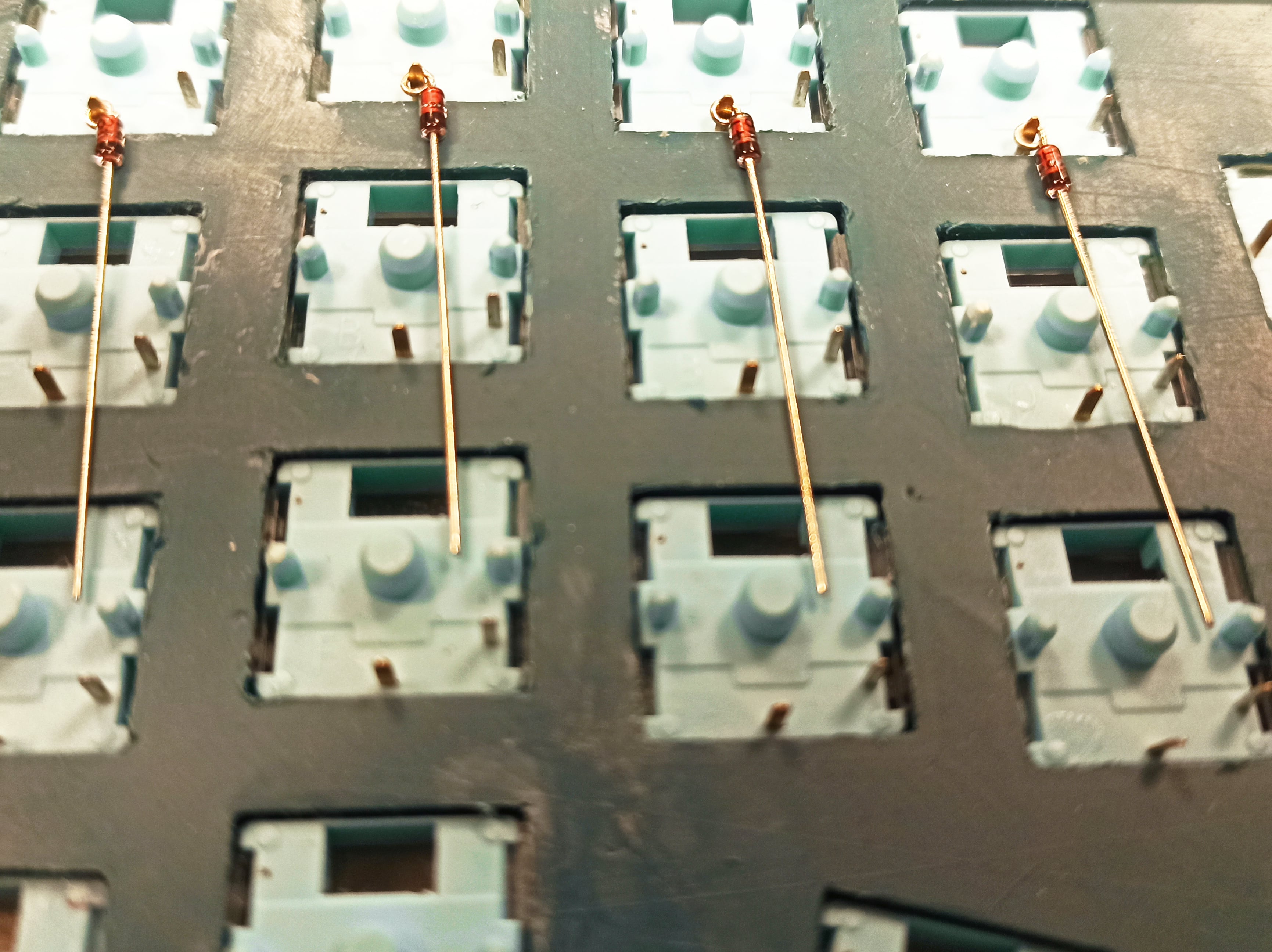
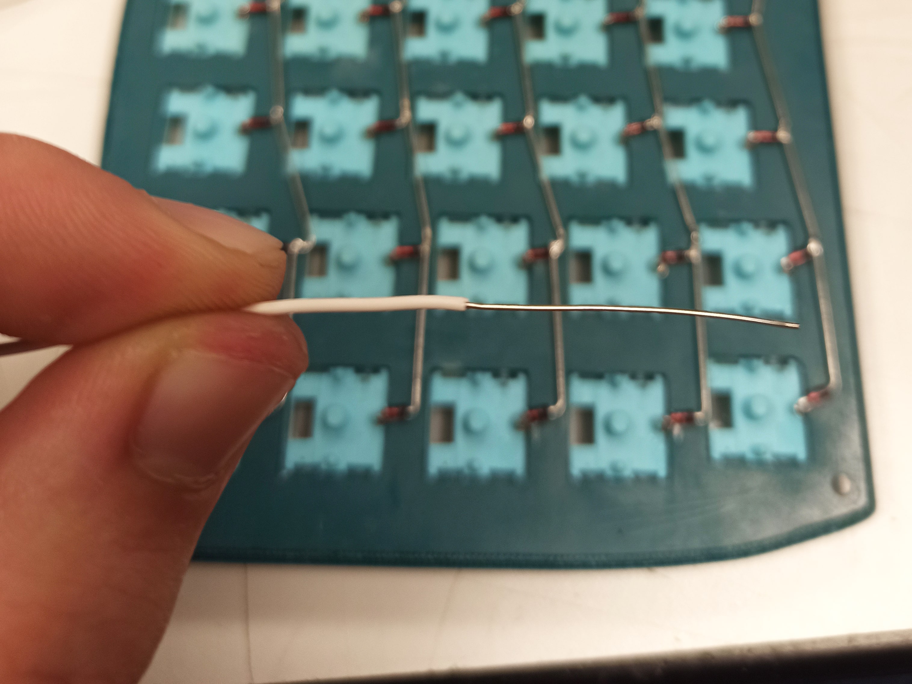
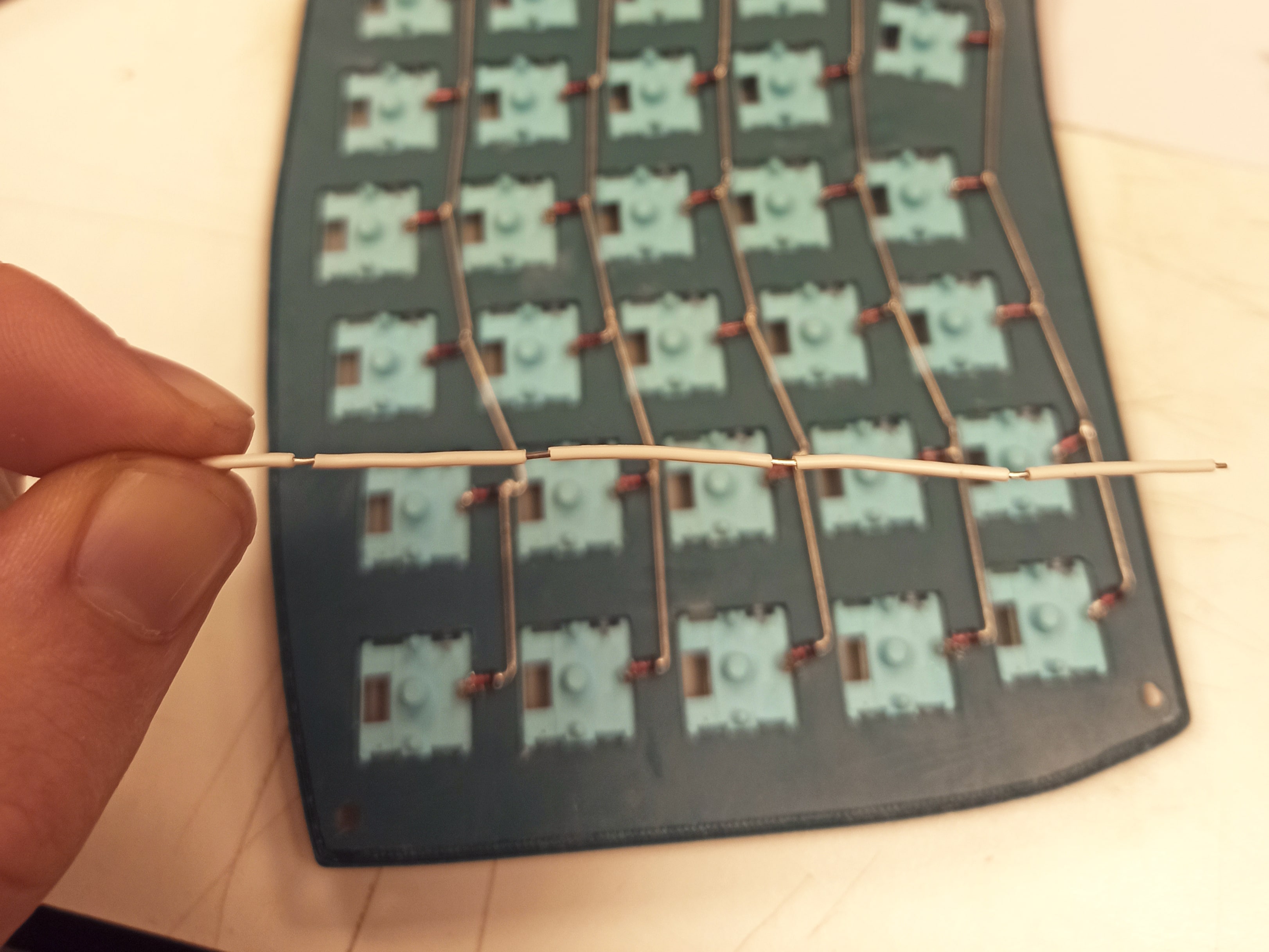
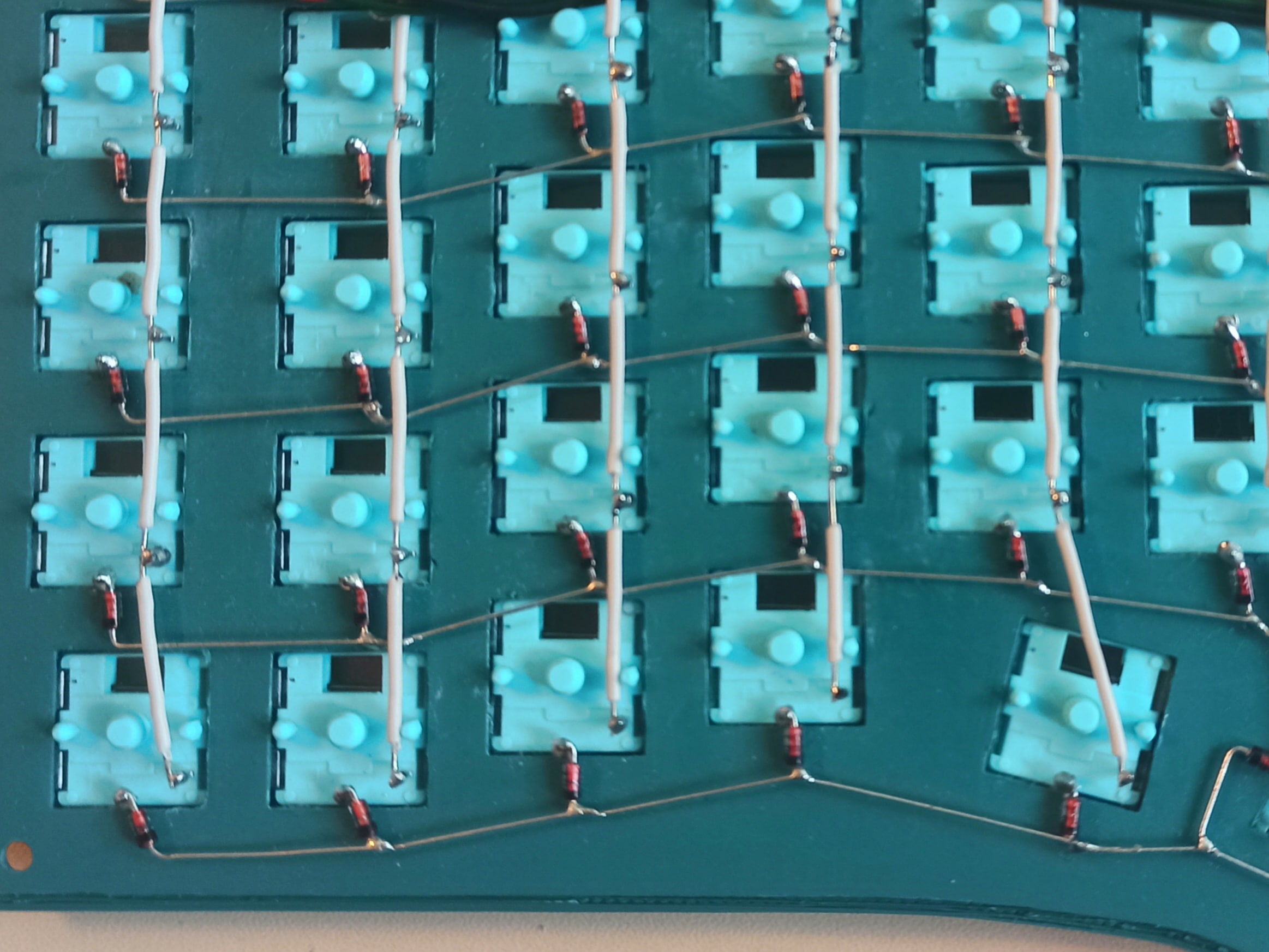
The cleanest wiring method I've come across so far is to loop each diode's cathode round one of the switch pins, then fold each of the anodes over to connect all the diodes on a given row. The columns on the other hand will need insulation to prevent the current from bypassing the switches. If we strip a section off the end, we can cut though the insulation at several points and slide them across so the conductor is exposed only where we need it.
The result is a neat looking matrix where no connection has any slack.
Wiring: Encoders
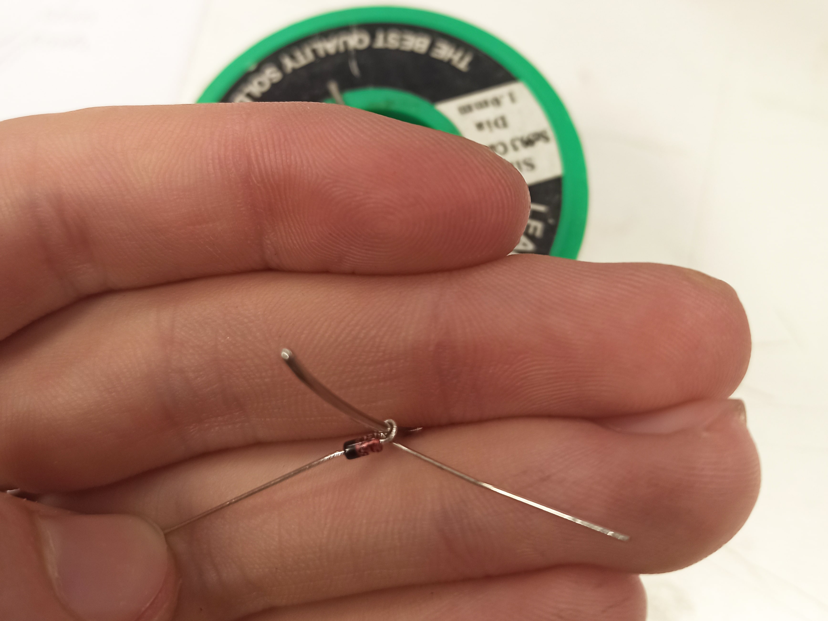
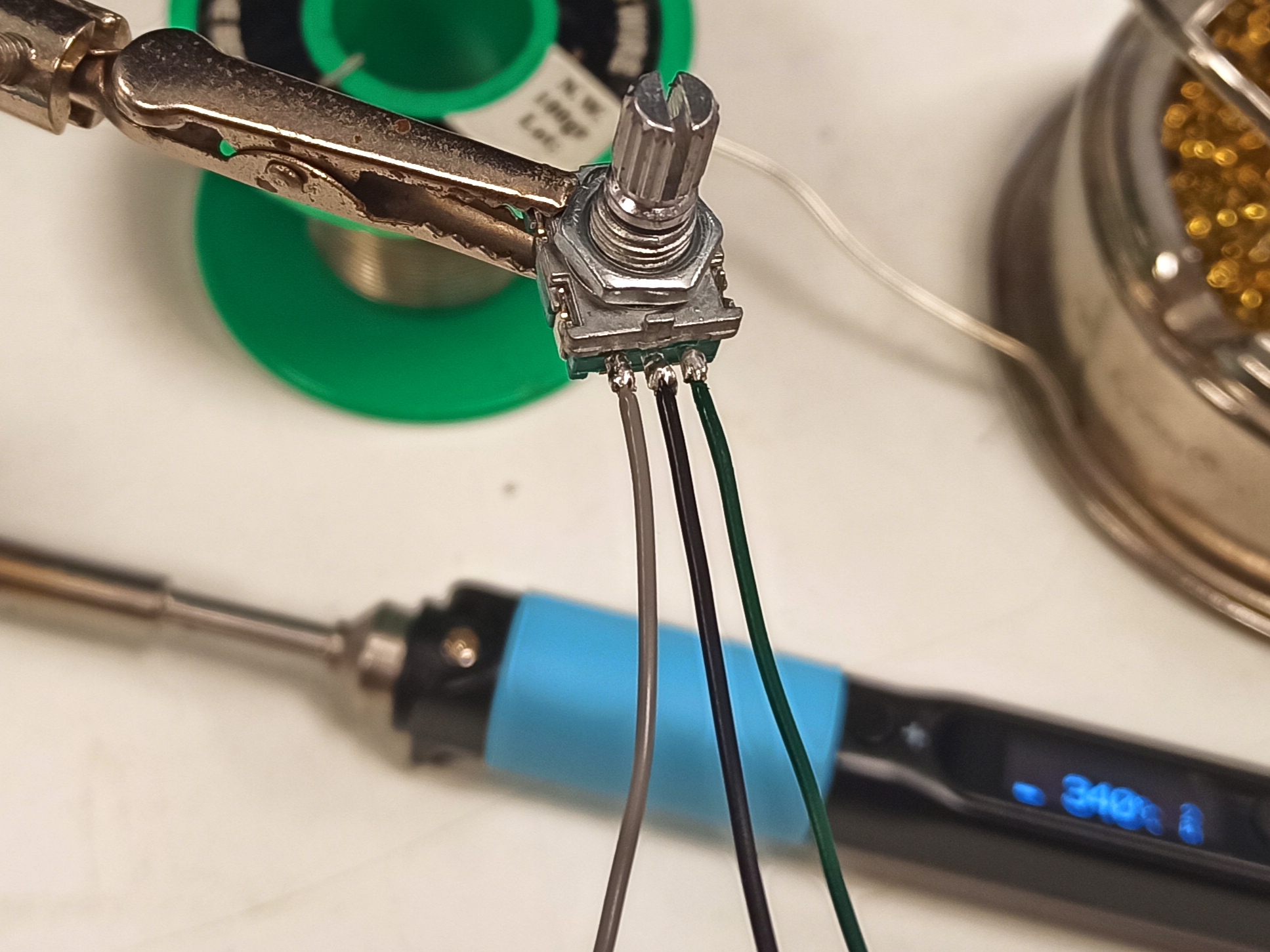
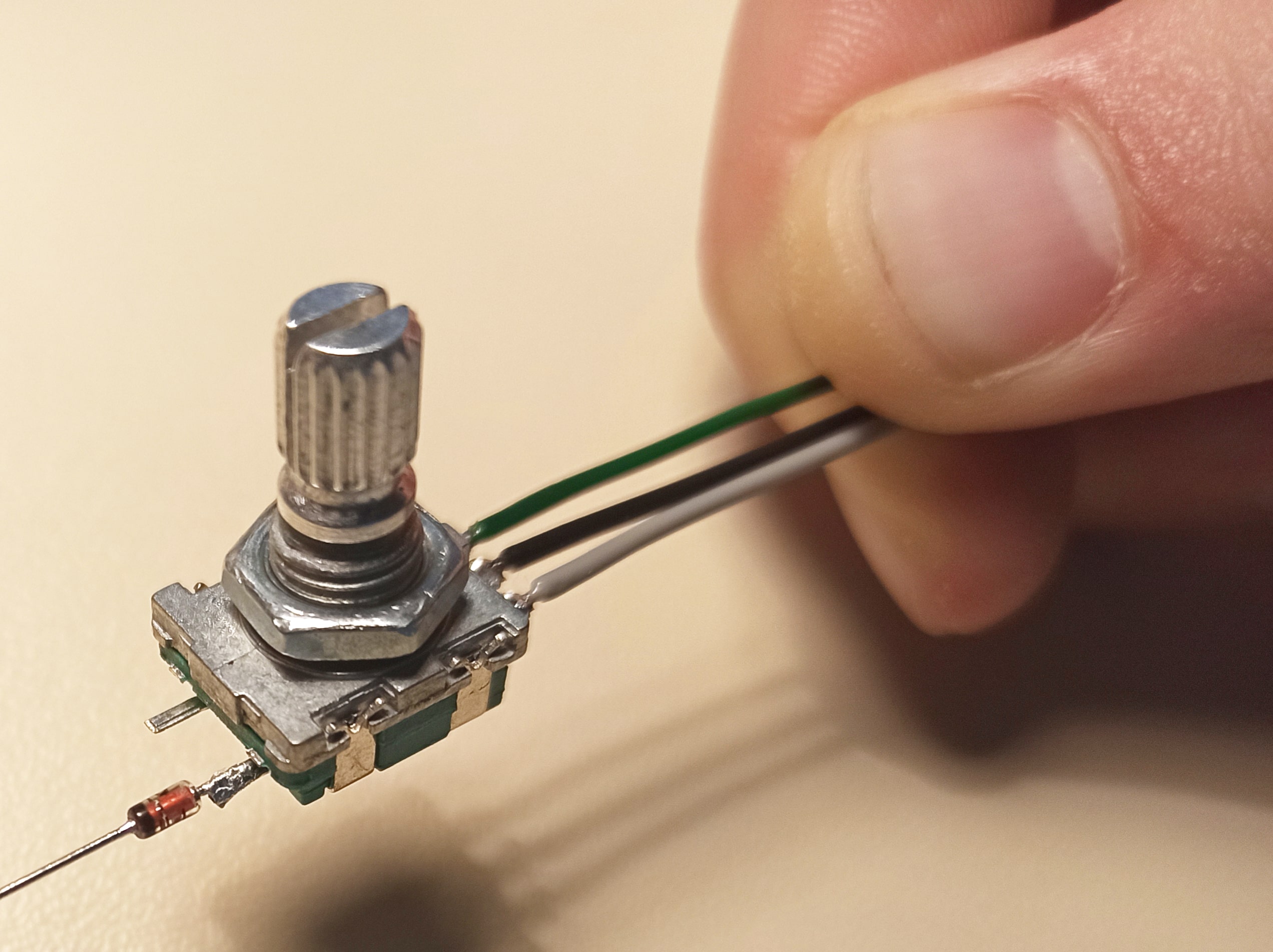
The encoders have 5 pins: 2 for the switch and 3 for the encoders.
A diode can be soldered to one of the switch pins, integrating the encoder into the matrix, while the other three pins can be connected to wires for later use.
Usually the center pin will be ground, and the pins on either side are labelled A and B.
They output square waves with a phase difference that allows us to figure out in which direction and by how much each encoder is rotated.
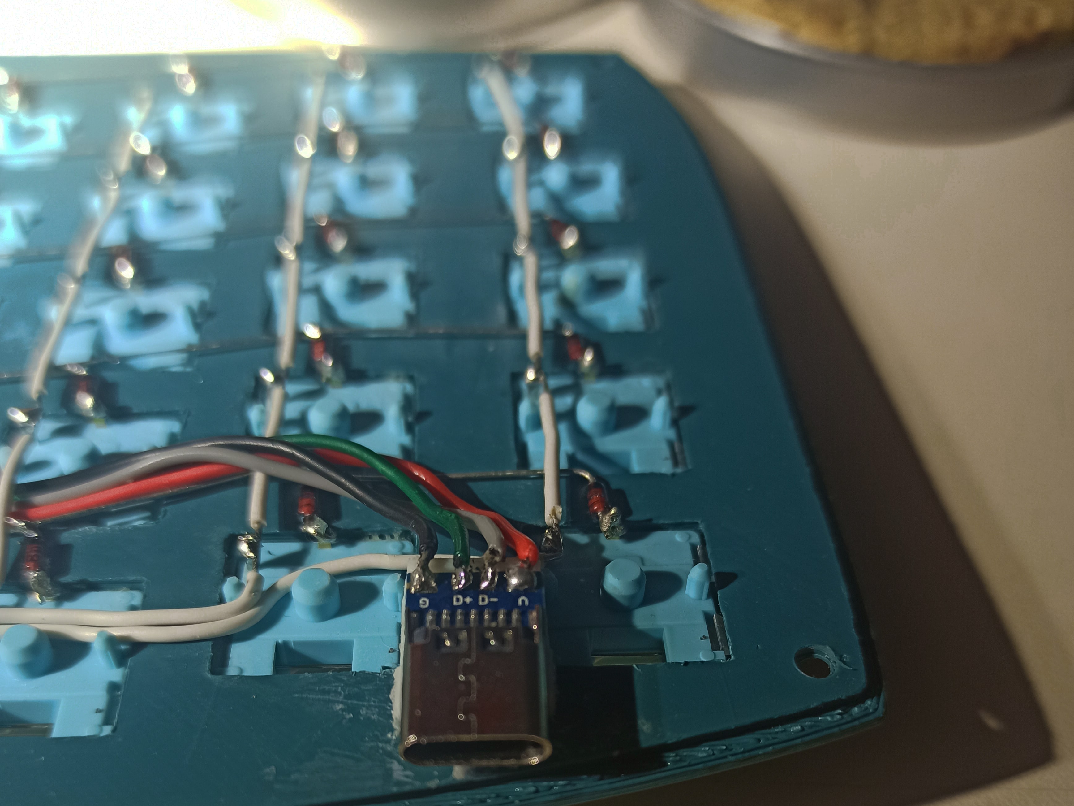
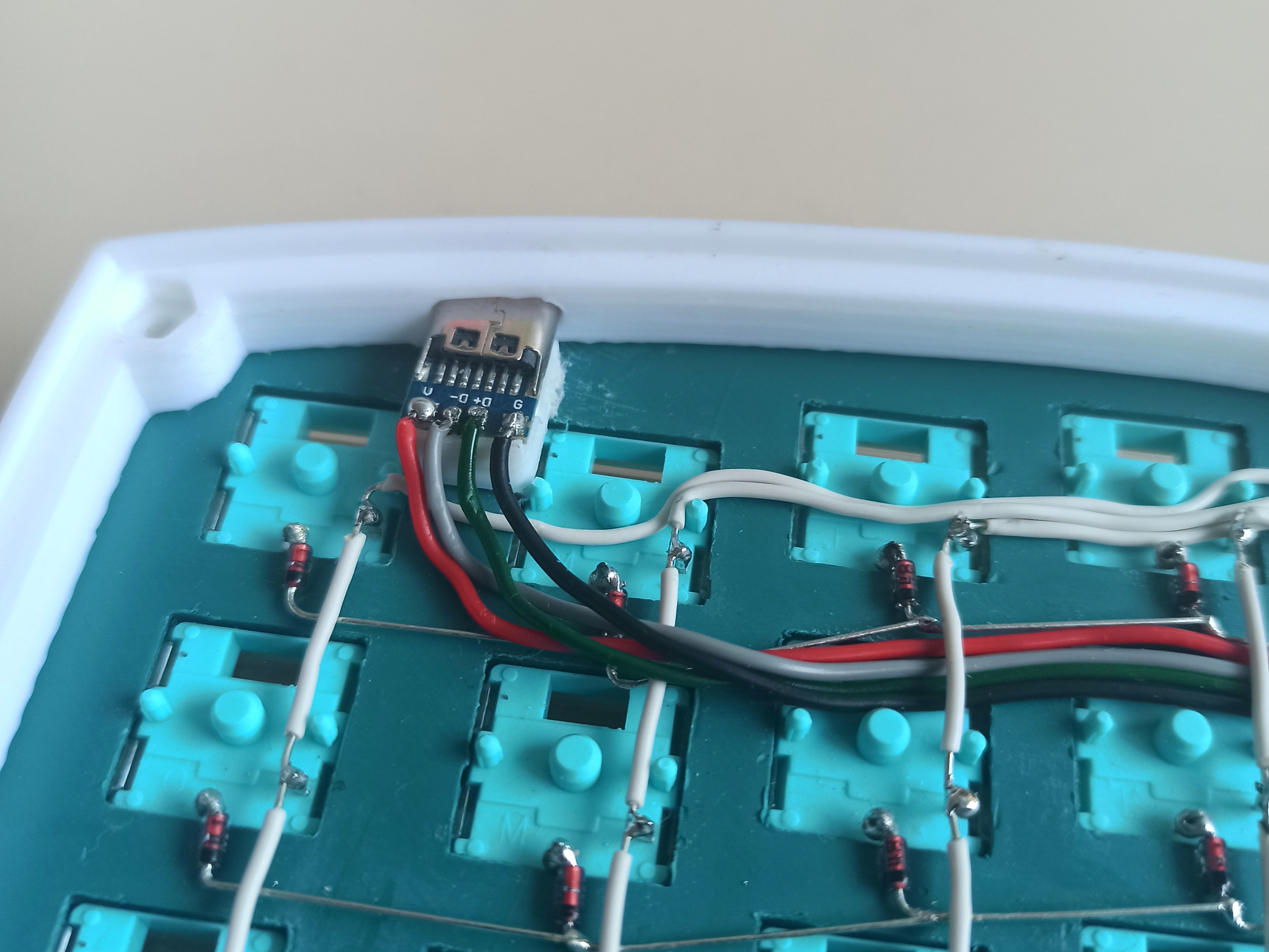
Wiring: USB port
The USB port comes with handy little solder pads which I've used frequently to convert micro-USB devices over the USB C.
There are only 4 pins so expect USB2.0 speeds but that's more than enough for this application.
The 5V, Gnd, Data + and Data - can be wired to a male micro-USB connector to plug directly into the Pro Micro board.
This way we don't take up any extra GPIOs and don't have to set up and manage a USB connection ourselves.
It's a good idea to try flashing something simple like a blink example to the board at this point, if it fails then you likely have the data wires swapped.
Despite only one side being plugged into the computer during day to day use, it's important both sides have a functional USB port since it will be needed in order to flash the configuration firmware later on, which happens more than you might expect, as you think of helpful features to add down the line.
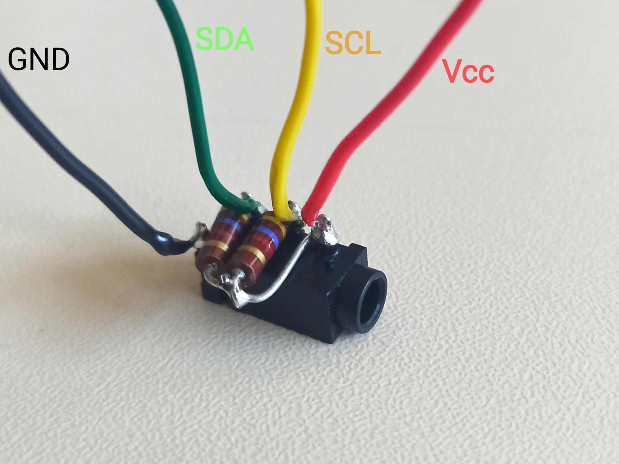
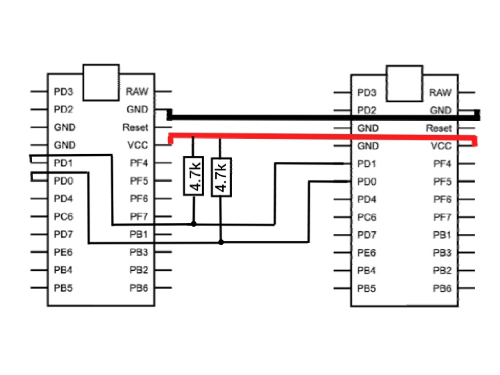
Wiring: I2C Jack
One of the two trrs connectors needs to have two resistors pulling the SCL and SDA wires to 5V. I did this on the master side but it makes no difference.
It's also worth giving some thought to the pinout, particularly where you place the 5V and Gnd to avoid frying the slave half if the cable somehow comes unplugged during use.
By having the sleeve be the 5V lead, we can be certain that it won't come into contact with any of the other pins in the connector during plugging/unplugging, and by putting Gnd on the tip, we're making sure the most harmless lead is the likely to be the one to contact any metal surface the unprotected connector could come into contact with.
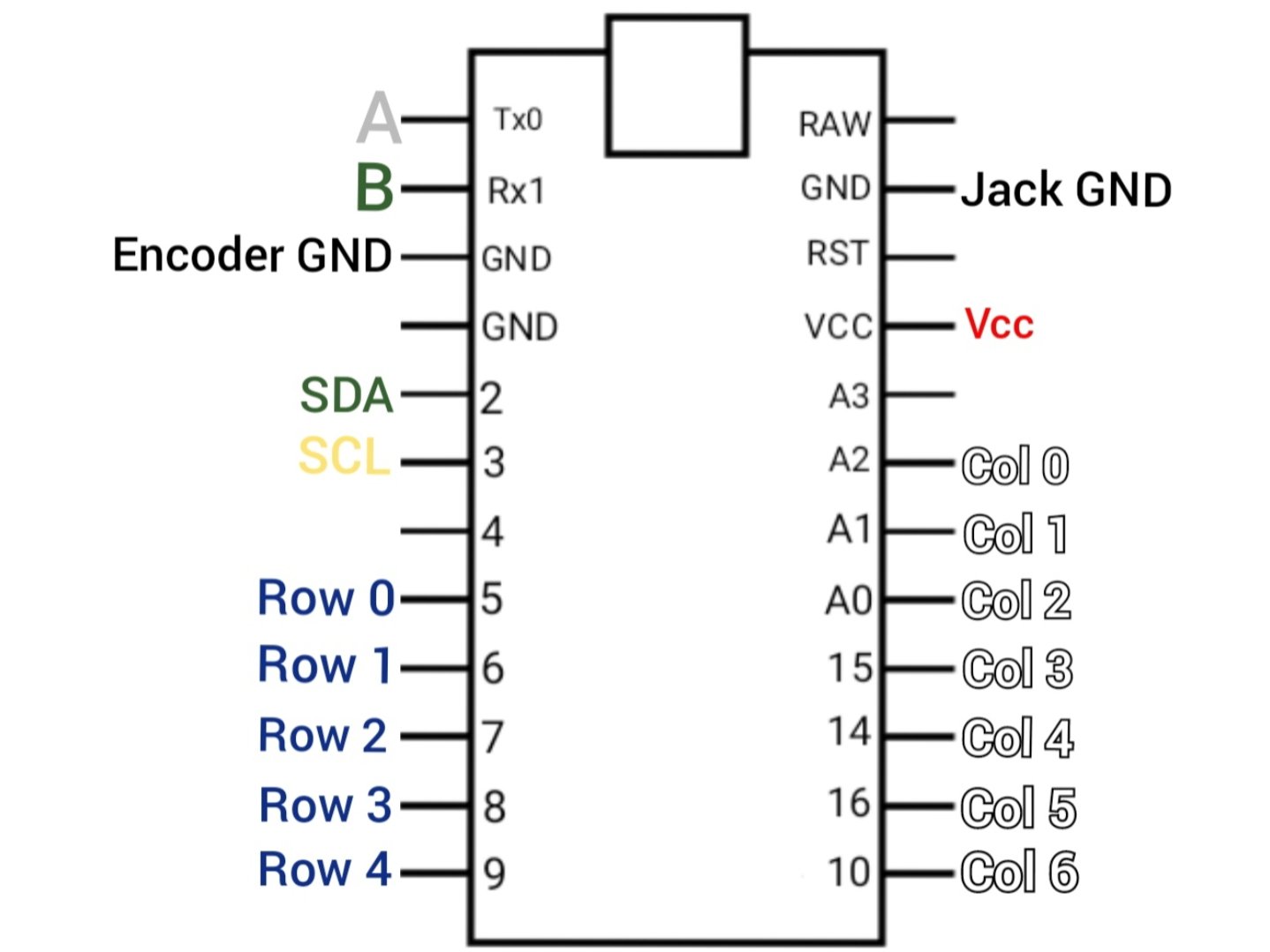
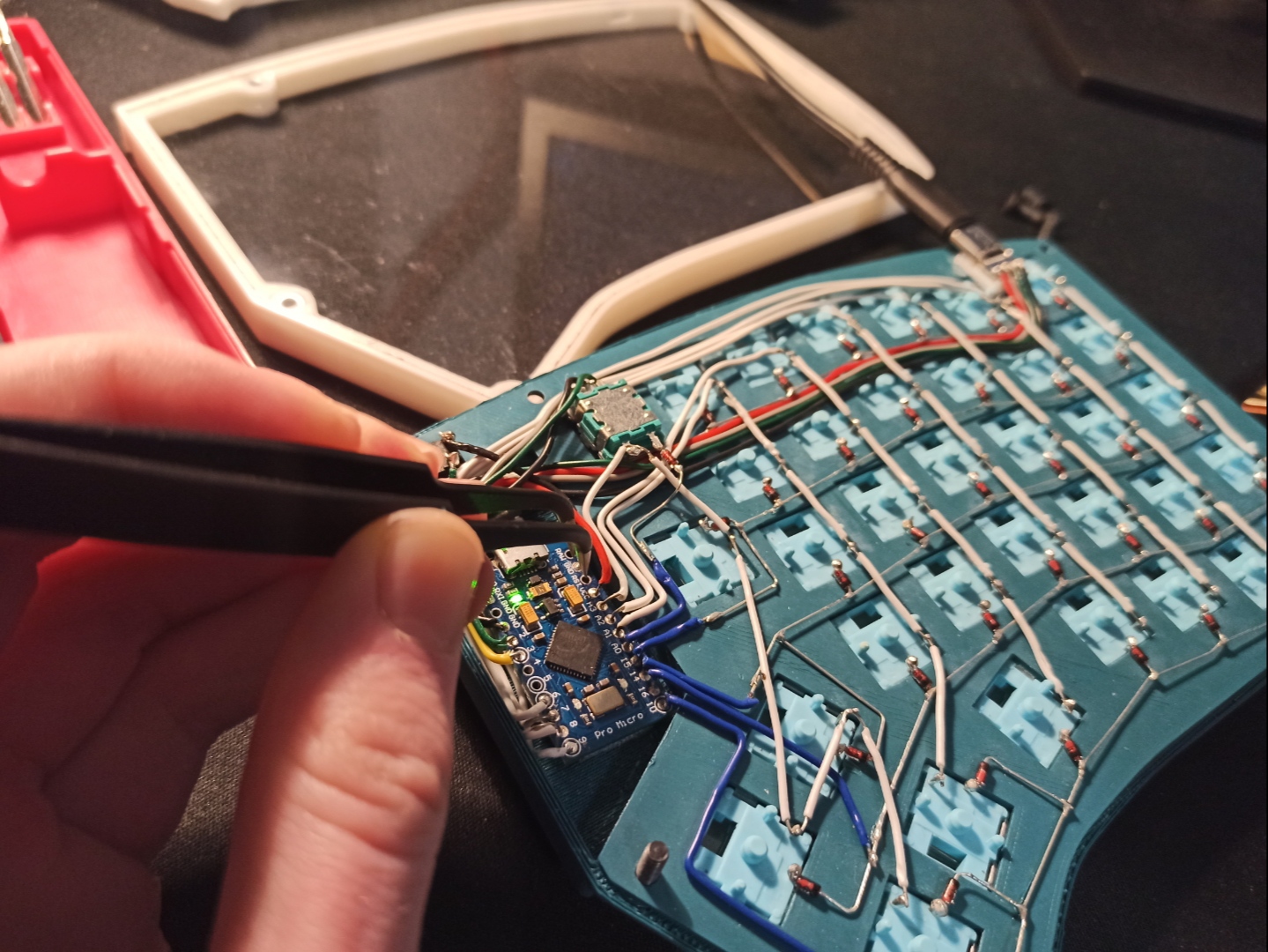
Wiring: Pro Micro
The Arduino Pro Micro Board has a total of 24 pins, including (very weak) power supplies, GPIOs, an I2C interface, and some other features we won't be using here.
A glance at the datasheet allows us to determine where each subassembly of our circuit can be connected, below is a diagram of the circuit I chose.
Keep in mind where you'll route each cable, as it's likely multiple wires will be squeezed into a tight section, especially if the cable management wasn't planned in advance and you're trying to save on space. Making this part look neat is challenging, it helps to have solid core wire as it can be bent reliably into shape but it does make the soldering more of a pain.
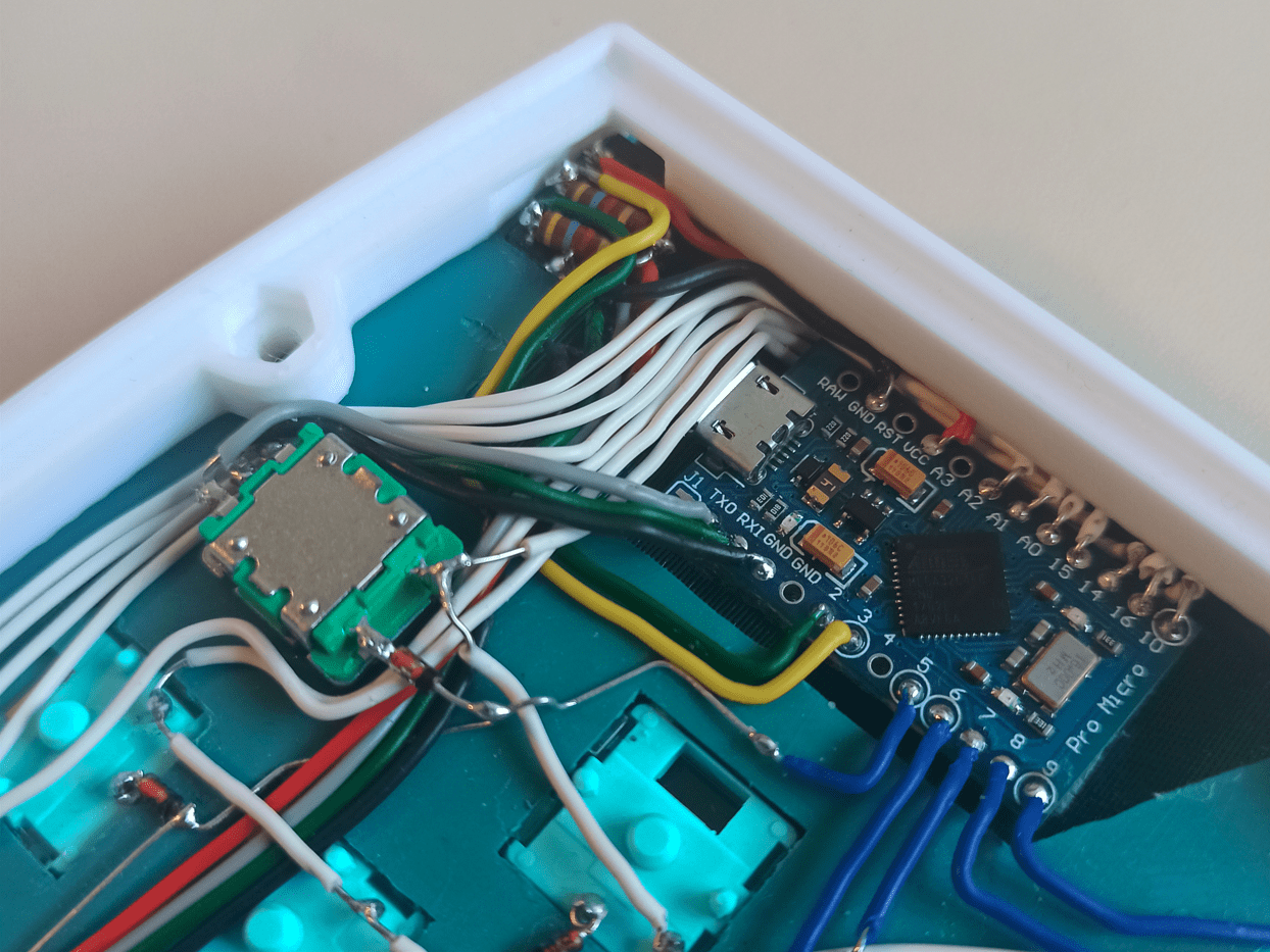
Finally, a finished half, now to do it all over again (decent podcast is highly recommended)
Configuration
Build Environment
There are a couple of tools that are used on top of a standard IDE:
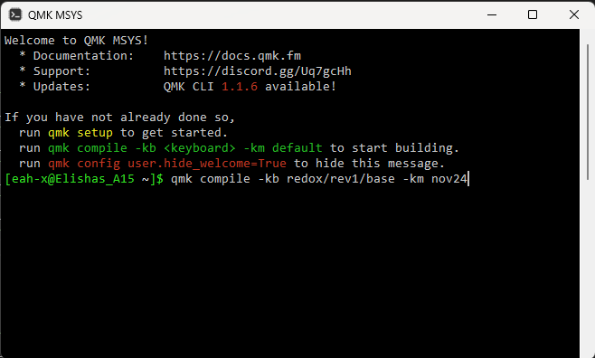
- QMK MSYS is both where we'll compile our code and what will help set up the file tree where all our firmware will lie
- QMK toolbox will serve as our firmware flasher to load the .hex file onto the keyboard itself
keymap.c
The keymap.c file is where the magic happens!
Its main function is to define the relative placement of each key in the matrix, and what each layer (see the features section) contains.
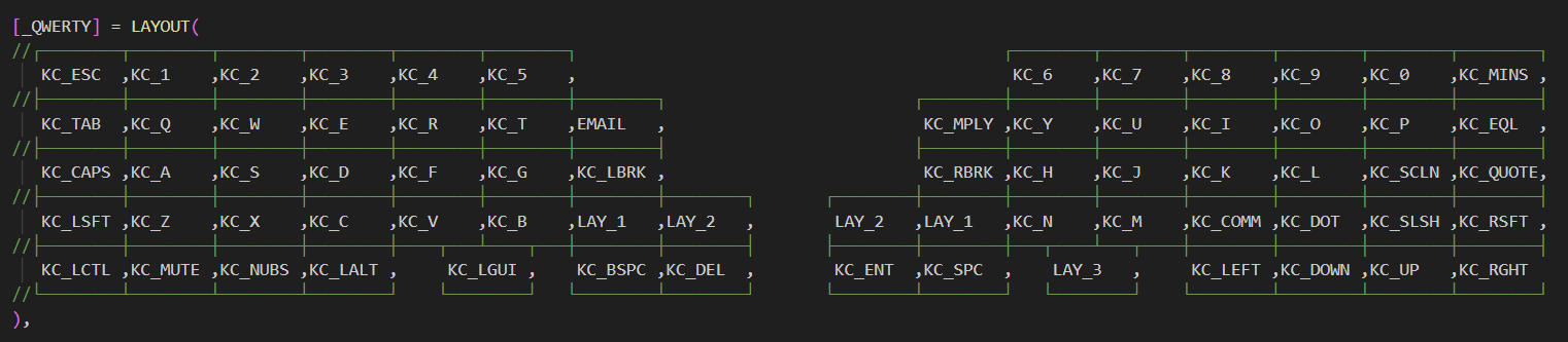
This is the base layer, each key position gets its own keycode. Most of these are fairly self explanatory: "KC_5" is both "5" and "%" when shift is pressed, and "LAY_1" shifts each key function to their assigned role on the first layer.
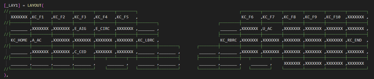
This layer contains more keycodes built into QMK so the number row can turn into the function keys.
A line means the key takes the function of the next layer down, in this case the base layer, so the layer has no effect on the key.
By repeating these principles, more layers can be created to allow for media functions, symbols and a number pad.
The other keycodes are personalised macros that call functions to automate series of keystrokes. In the case of "E_AIG" for example, the ALT key is "held" whilst the code "0233" is sent, but of course this happens too quickly for the it to be noticeable and the "é" symbol immediately appears instead.
This is the workaround for getting accents when the computer's keyboard is set to "UK"!
On the topic of workarounds, keymap.c is also where the functions that process the encoders are. The right one simply sends a "KC_VOLU" or "KC_VOLD" for every position, depending on the direction. The left one somehow started triggering this function also, despite being on a different microcontroller. I suspect it might have something to do with the pins sharing the same name. After trying different solutions for a couple of hours, on top of emulating the Alt+tab combination I also set it to alter the volume in the other direction to compensate. This results in a stable volume, but if you look closely on the vertical videos in the features section, you can see the volume slider appear on screen in the demo! Good enough for now!
Configuration Files
Especially due to the fact the keyboard is both split and a custom circuit, more files are needed to specify how the hardware is assembled:
- Knowing the keyboard is a split design means QMK needs to divide the matrix into two, and expect two sets of pins for the rows/columns
- The pins specified aren't the simplified Arduino pins, but instead the ATmega32U4 pins whose addresses reflect the registers and internal buses they are assigned to
- Which side is the master, and how it is to be recognised. In this case the master is the right hand, and the halves can be differentiated by the USB connection only the master has
- The direction of the diodes, which determines whether the key strokes are read on the rows or the columns
- Encoder resolutions, information regarding the bus over which both halves communicate, etc, ...
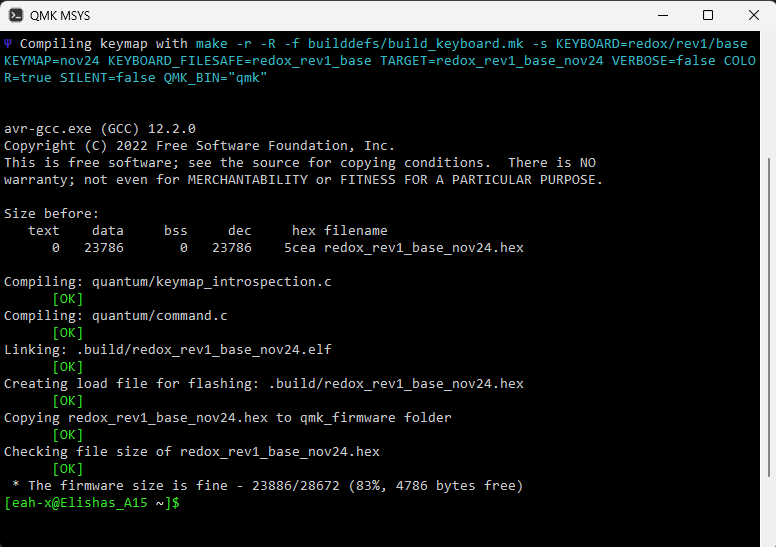
Compiling Code
Compiling is fairly straightforward, with simple commands and checks that either produce errors that are vague and hard to fix, or release a dash of neon green dopamine once it all checks out!
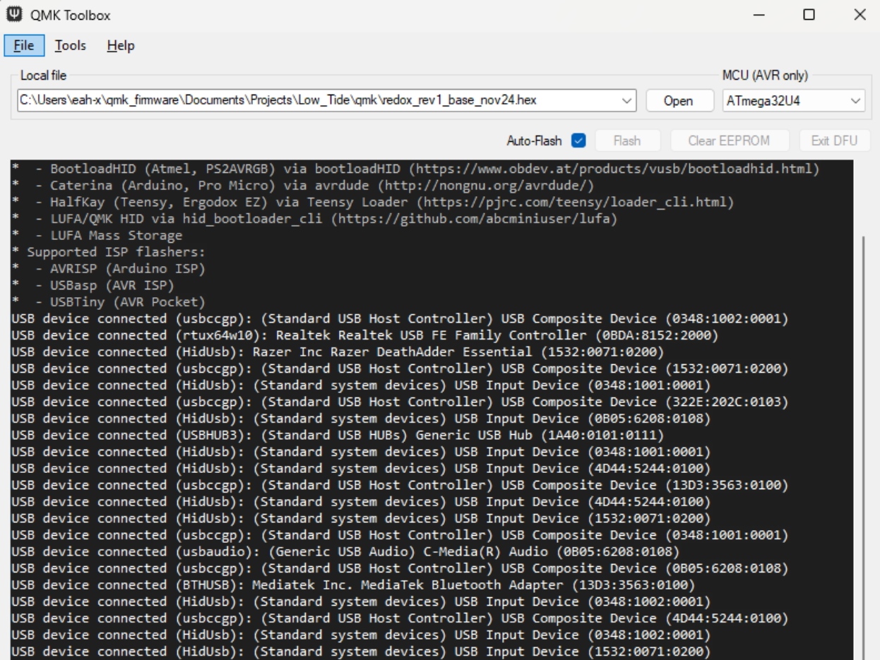
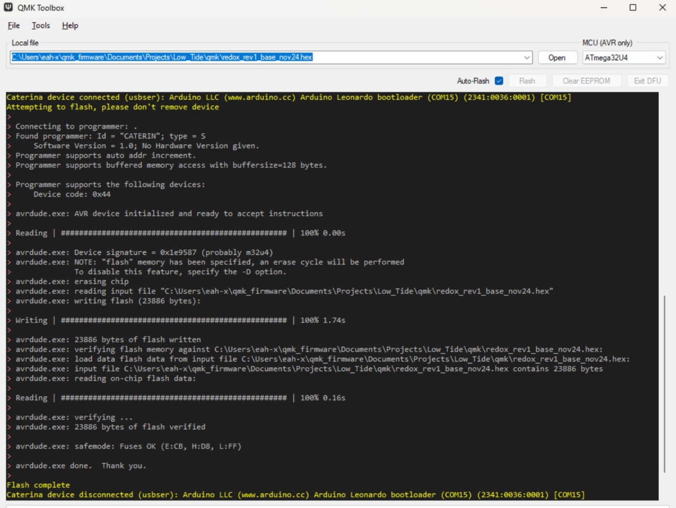
Flashing Code
The same .hex file produced by QMK MSYS can now be flashed to both halves of the keyboard with the help of QMK toolbox
The procedure is as easy as putting the microcontrollers into bootloader mode by shorting the reset pin to Gnd twice in quick succession, then letting the "autoflash" feature do its thing!
That's pretty much it: a working customised keyboard that's a delight to type on for longer than I probably should.
Adapting to both a new layout, form factor, and learning to touch type for the first time after using computers for well over a decade took a good couple of weeks.
Now a few months in I can confidently say my speed on the Low Tide has surpassed my plank speed, and although my accuracy has taken a bit of a hit it's a compromise worth making since I now have my eyes set on my monitor 100% of the time so I instantly notice mistakes instead of when reading through again. A side effect of the split form factor is its compact size. Since I started wanting to bring it with me more and more when working away from my desk I designed this travel spacer the halves can slot into, with the cables contained within.
I've really taken a liking to this since it drastically protects the keys and makes the bottom feel less flimsy despite being laser cut from the same 1.5mm plexiglass as the window in my Key Companion project.
Thank you for reading this far.
I very much enjoyed this project that will serve as a foundation of perseverance and creativity going forwards.
In the words of Mr. Zack Freedman: "The project that will continue to pay off, because it will be used to make every other project from this point on!"
I very much enjoyed this project that will serve as a foundation of perseverance and creativity going forwards.
In the words of Mr. Zack Freedman: "The project that will continue to pay off, because it will be used to make every other project from this point on!"