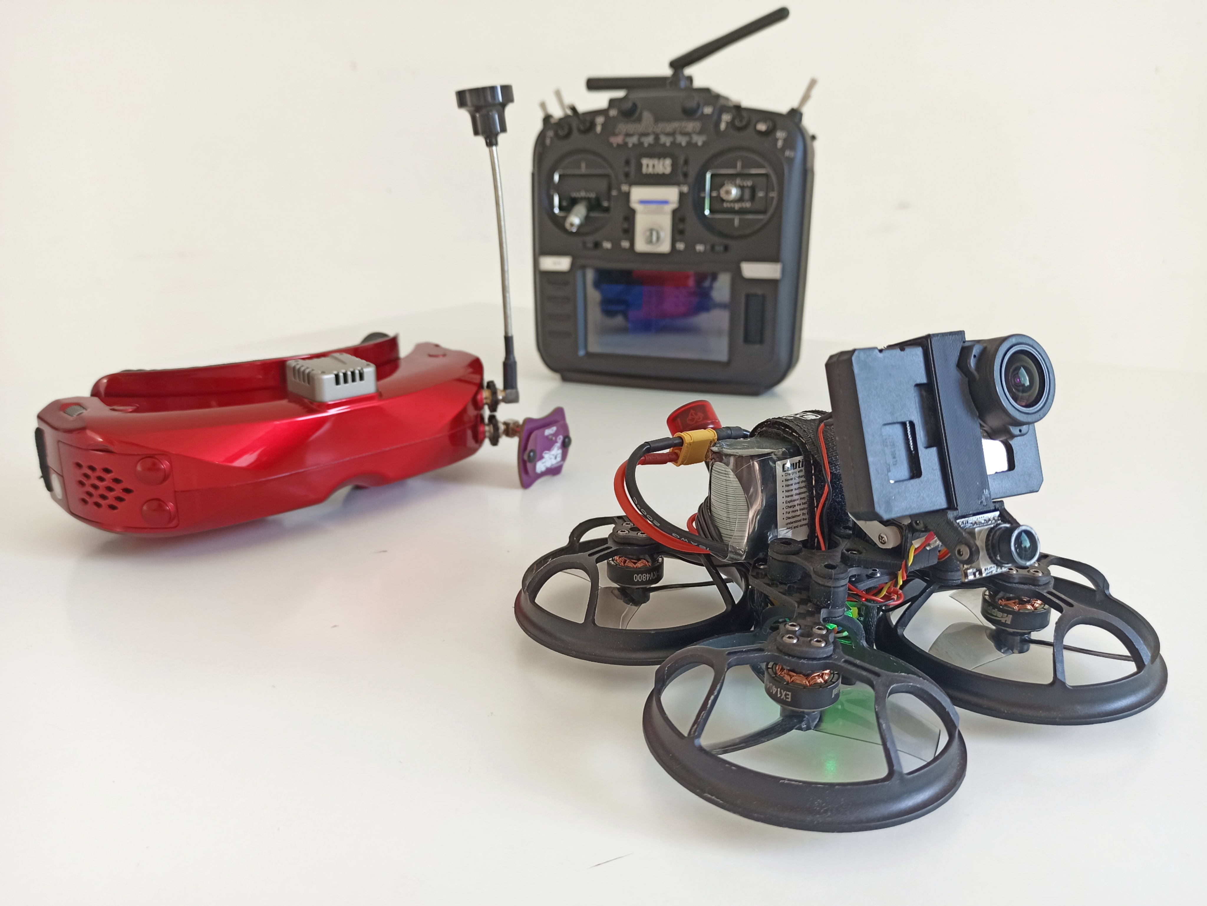
An Agile, Versatile, Camera in the Sky
Tracker Whoop is a very special drone that takes advantage of the agility and precision of FPV drones, whilst also solving some of their biggest drawbacks.
It is flown from a pair of goggles that display a live video feed to the pilot.
This, coupled with a headtracking system (where the camera follows the pilot's head movements on the pitch axis for reasons we'll get into later)
makes flying incredibly precise and immersive.
Now consider its ability to capture 4k 60fps video, its size—about that of a hand—while still weighing well under 250g with protected propellers,
and it becomes an incredibly versatile cinematography tool capable of shots impossible with any other platform.
I started making and flying FPV (short for First Person View) drones in late 2017. Over the (almost) 8 years since then, I've developed a basic understanding of radio transmitters & polarised waves, tuning PID loops, composite materials & vibration dampening, flight controller firmware, various ESC and control link protocols, the list goes on and on...
In a way this project showcases some of the aforementioned elements, and just what is possible with this technology: the ability to make custom UAVs tailored to extremely specific use cases.

In order to achieve the shots in the showreel above, this project relies on 3 subsystems of particular interest.
The following section titles are clickable shortcuts to take you to their respective segments:
Quadcopter Platform
A Cinewhoop
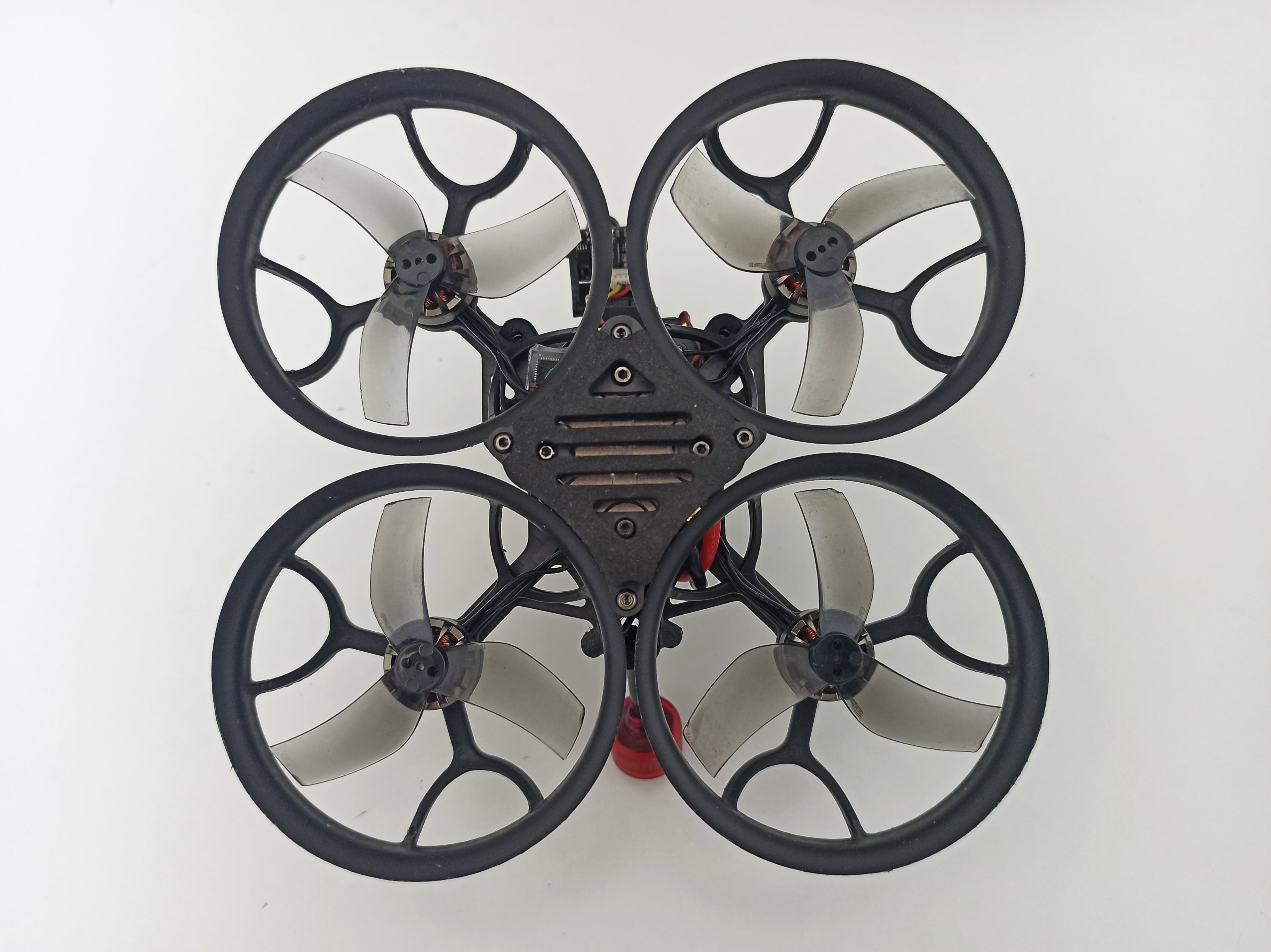
The Tracker Whoop fits into a category of FPV drones known as cinewhoops.
They're generally used for slow and controlled flying in tight spaces or around people, hence the enclosed propellers, in rings known as ducts.
Though they in theory result in increased thrust by preventing vortices from forming on the tips of the propellers,
the gap between the blades and the duct is too large for this to really come into play, so they instead act primarily as propeller guards.
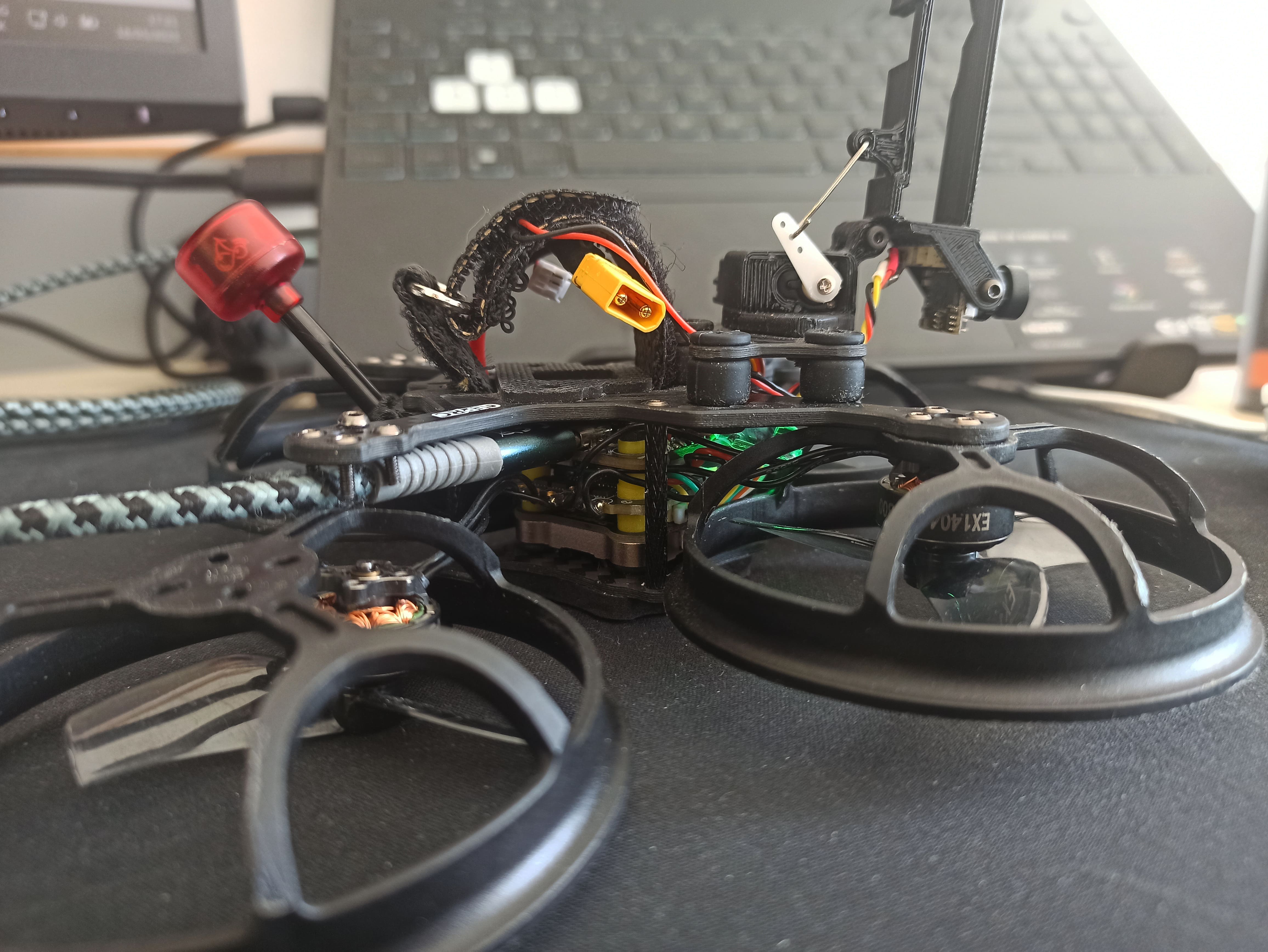
Cinewhoops have grown in recent years from unreliable experiments to a trusted FPV tool. As a result, more parts than ever are readily available which is why I chose the Cinelog 25 frame by GepRC as a base for this project. It's made up of a stiff 2.5mm carbon plate and interchangeable injected molded ducts, neither of which I currently have the means to manufacture.
They did a good job though, the name refers to the propeller diameter being 2.5 inches which gives it a small footprint, and there are options for mounting various standards of electronics in various orientations. The motors are also mounted on the underside, making for cleaner airflow (unobstructed by the arms).
The main selling point for me though was the addition of a vibration isolated plate at the front where a camera can be mounted in order to get smooth footage. This plate rides on isolation grommets that compress and filter out high frequency oscillations from making their way into the camera feed. This would cause an undesirable effect known as "jello" distorting the image.
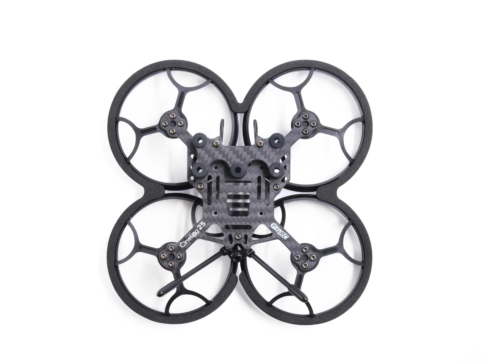
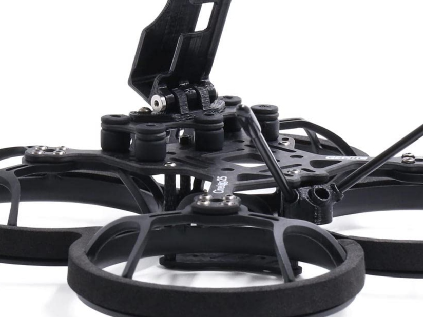
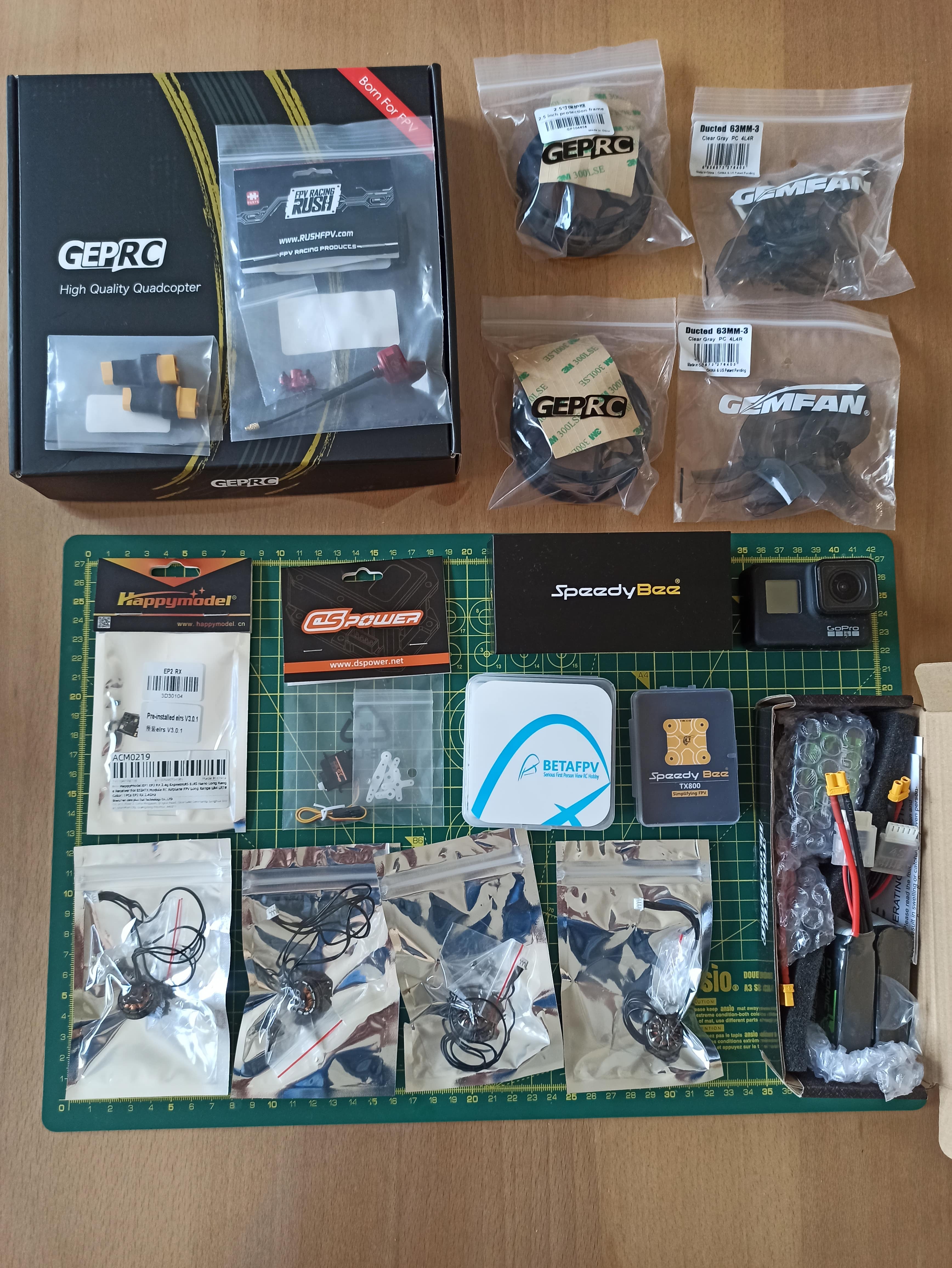
(Frame images from GepRC)
The following schematic sums up the overall wiring for context.
The flight controller, running on an STM32 F405 microcontroller is very much the center of the electronics.
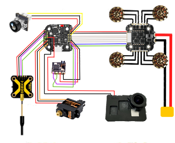 It has pads to power and communicate with the different peripherals over various standards:
- The camera is a 4:3 aspect ratio CMOS sensor based module that takes 5V and outputs analog video (over the yellow wire in the top left here)
- The 5.8GHz video transmitter is connected over a UART (bottom left). This allows the output power and frequency to be set through the flight controller.
- The receiver (square below the FC) is also connected via UART. It receives 2.4GHz packets that follow the Open Source "Express LRS" protocol, boasting incredible range and penetration for a given power. This means we can get away with a tiny ceramic cube antenna that doesn't need to be carefully mounted outside the frame.
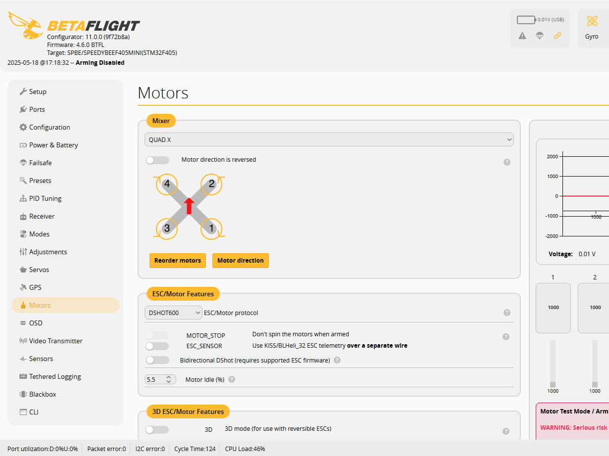
- The Electronic Speed Controller (ESC) communicates over a robust protocol known as Dshot. There is one signal wire per motor, and in turn the ESC supplies battery voltage power to the FC as well as a current measurement (used for example in the On Screen Display)
- I'll come back to the servo motor and GoPro camera later...
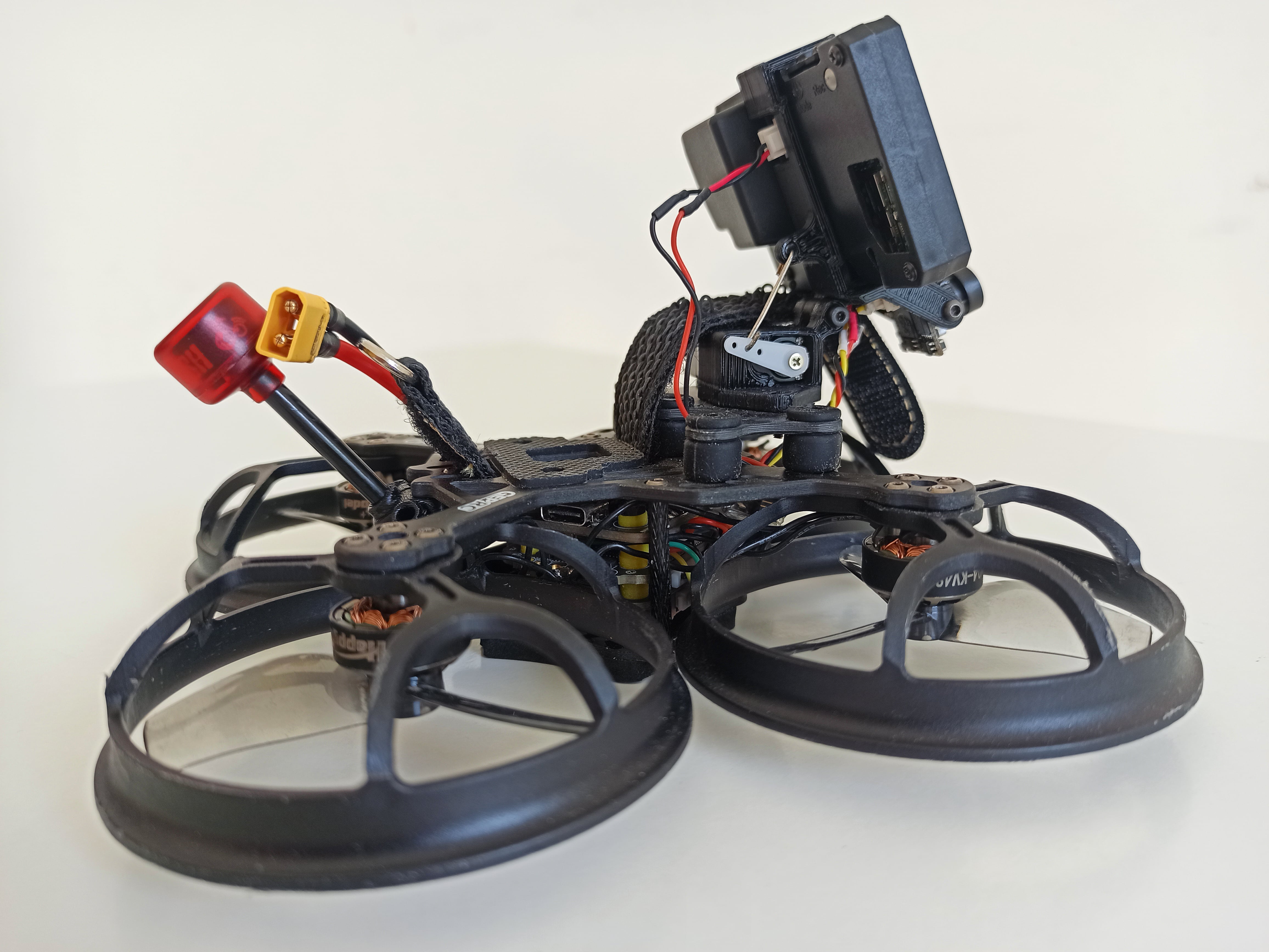
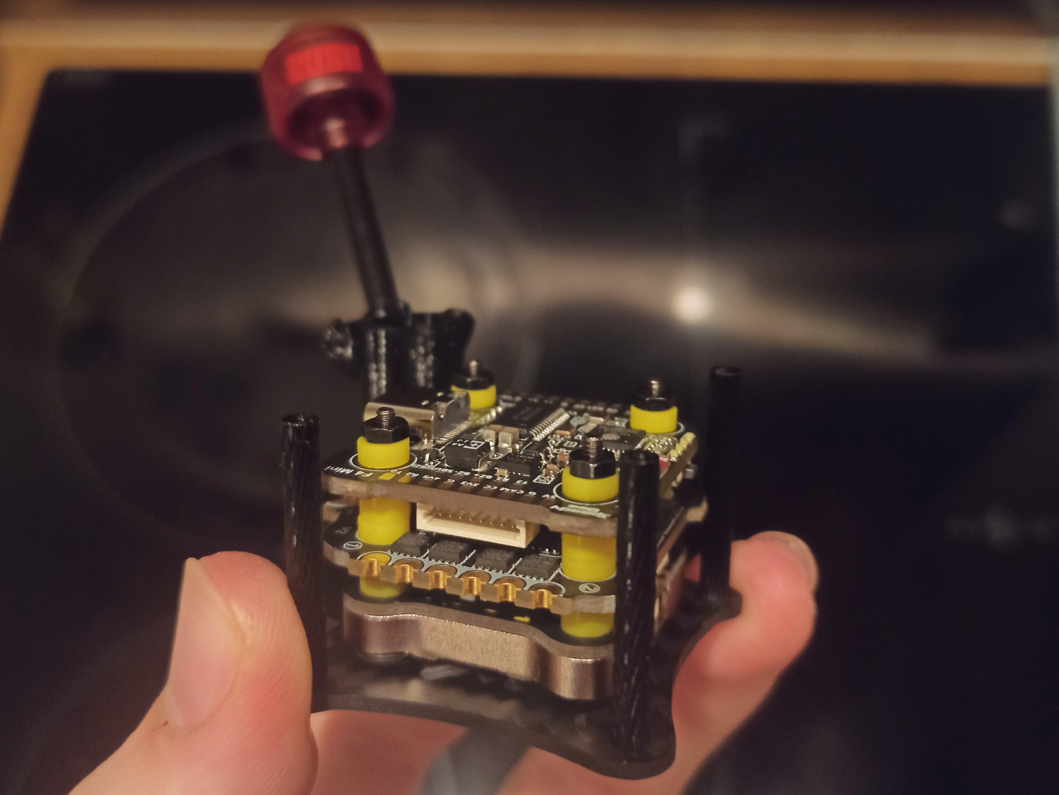
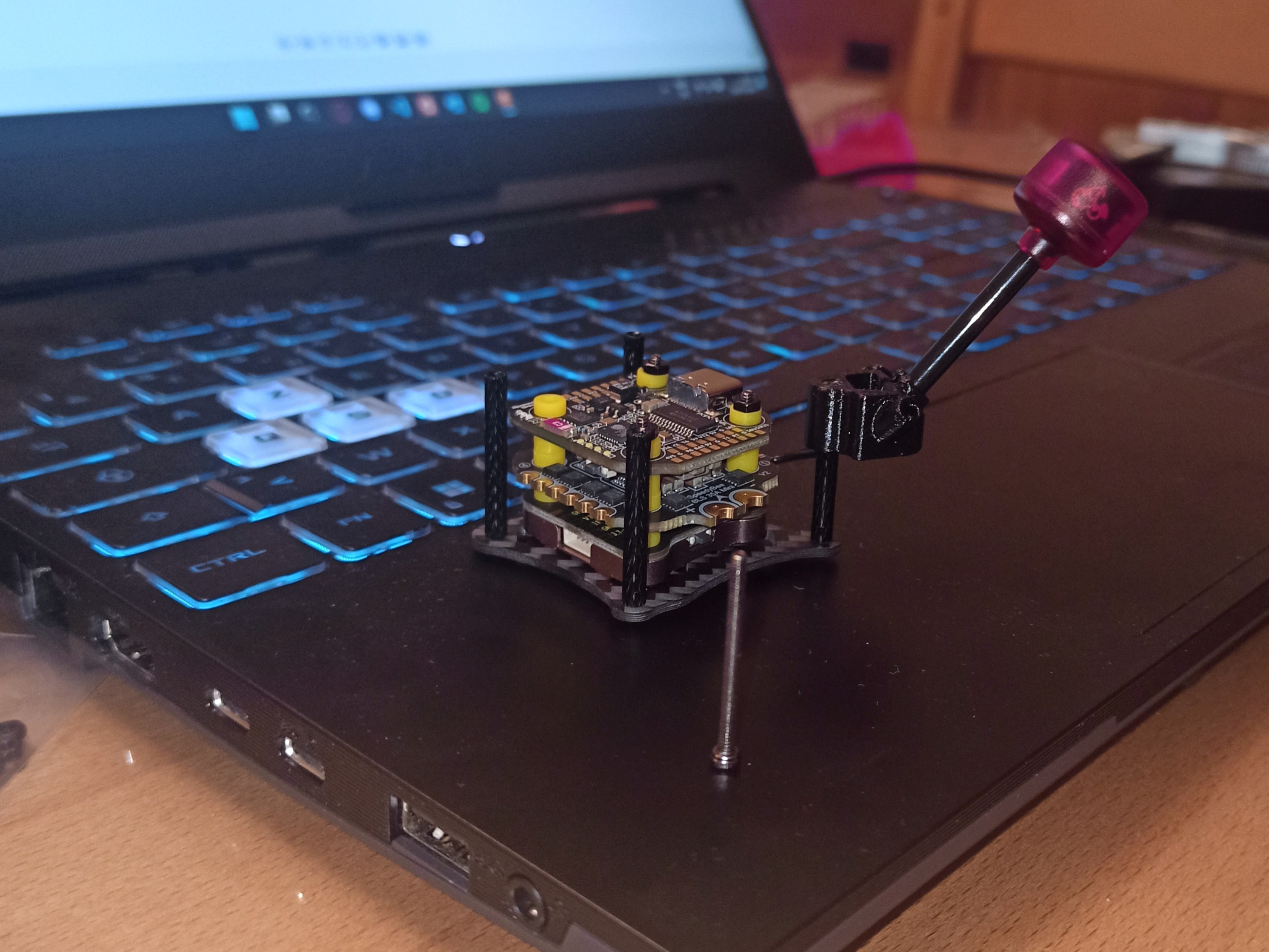
Stack
The assembly made up of the FC and ESC is known as the stack.
Here they have to be mounted one above the other with long m2 hardware, at a 45 degree angle between the ducts.
I also opted to mount my video transmitter (VTX) there too, on the bottom where the heatsink stood the best chance of getting both decent airflow and a clear route for the antenna.
Powertrain
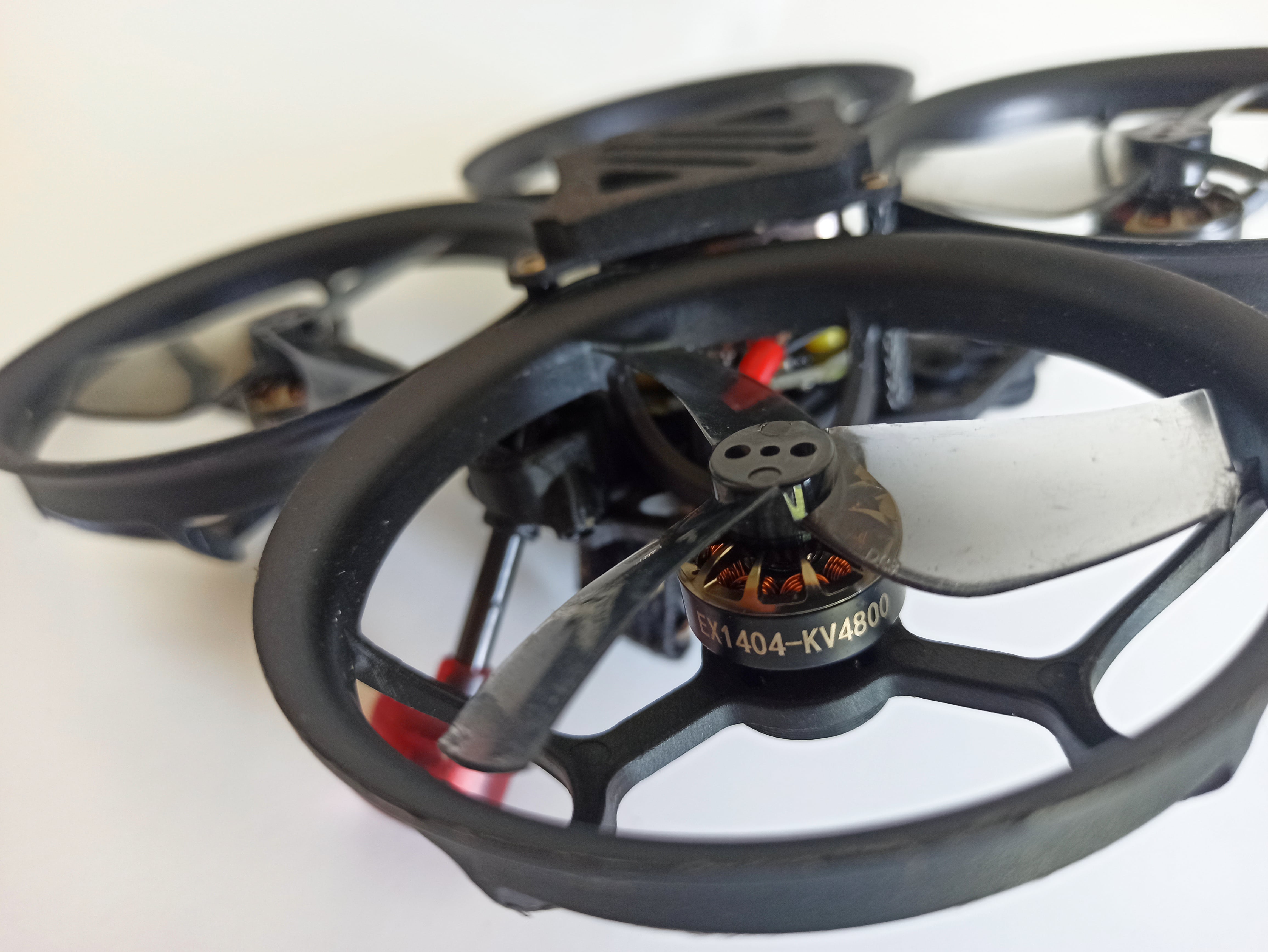
The powertrain is composed of four 1404 size motors spinning the tri-bladed variant of the D63 propeller.
The motors are 4800kv for some headroom in the throttle in case I need to quickly punch out to avoid something.
I run them off a 4 cell Lithium Polymer battery, this theoretically results in an approximate top speed in the vicinity of 80 000 rpm.
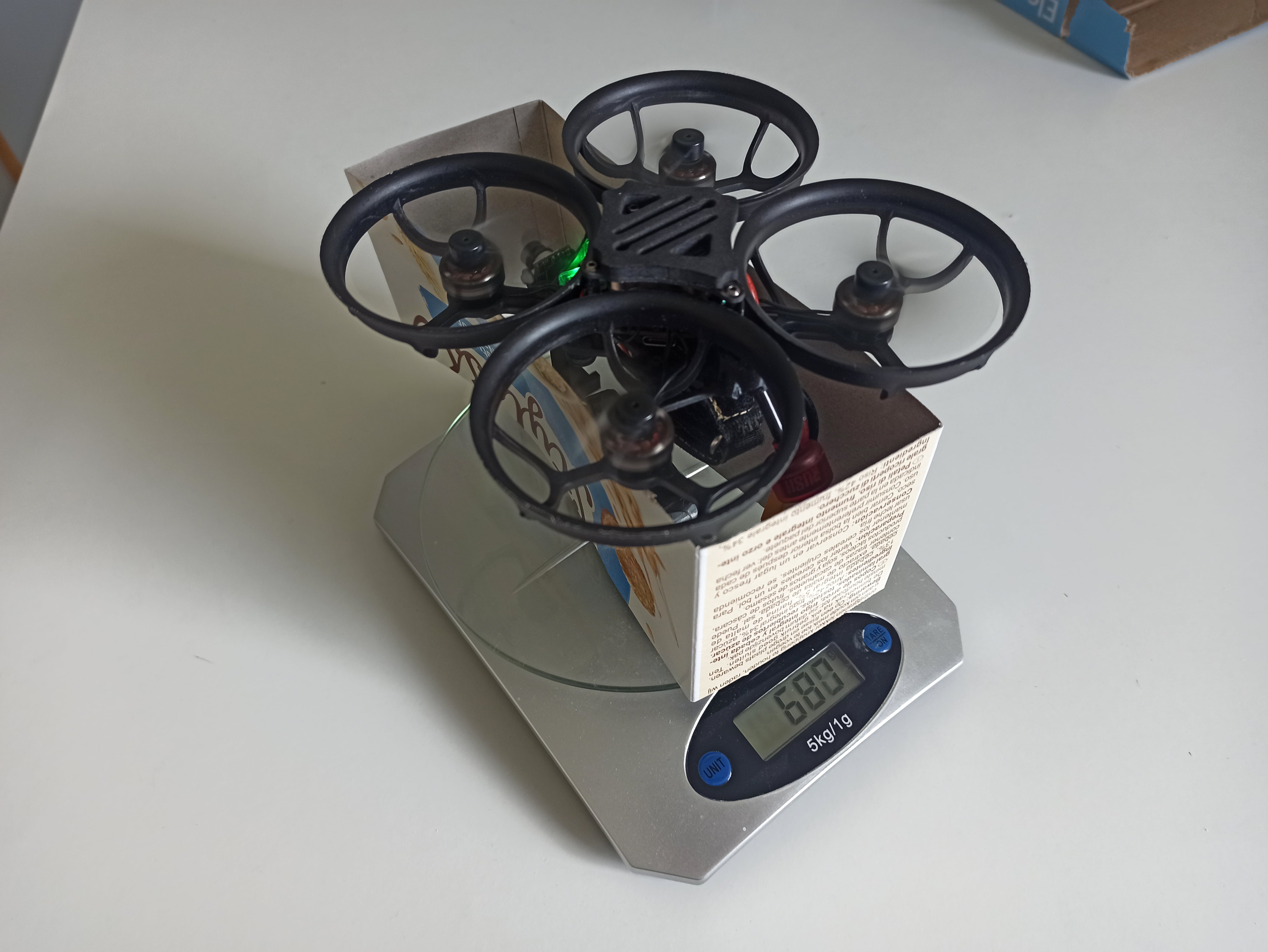
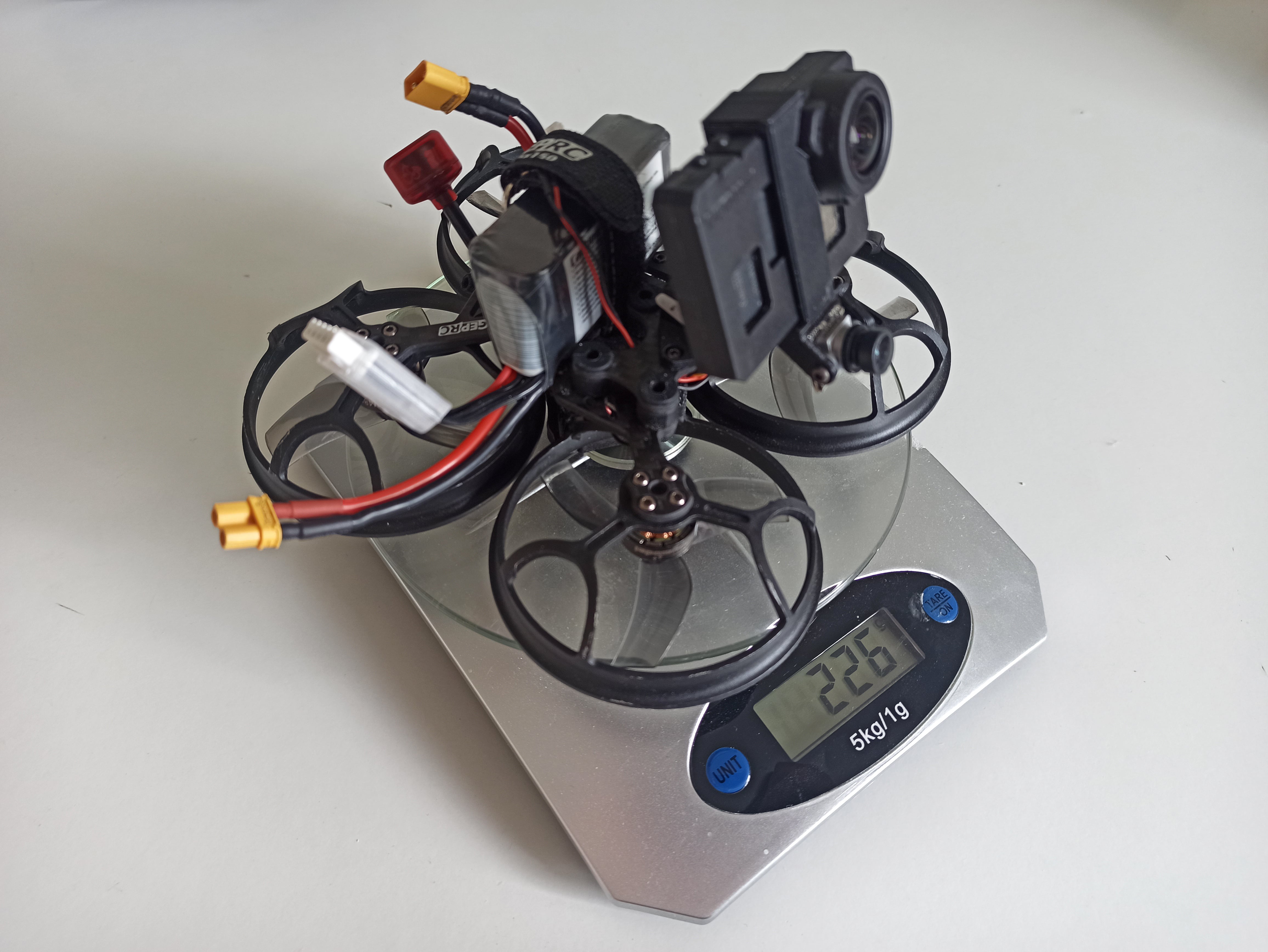
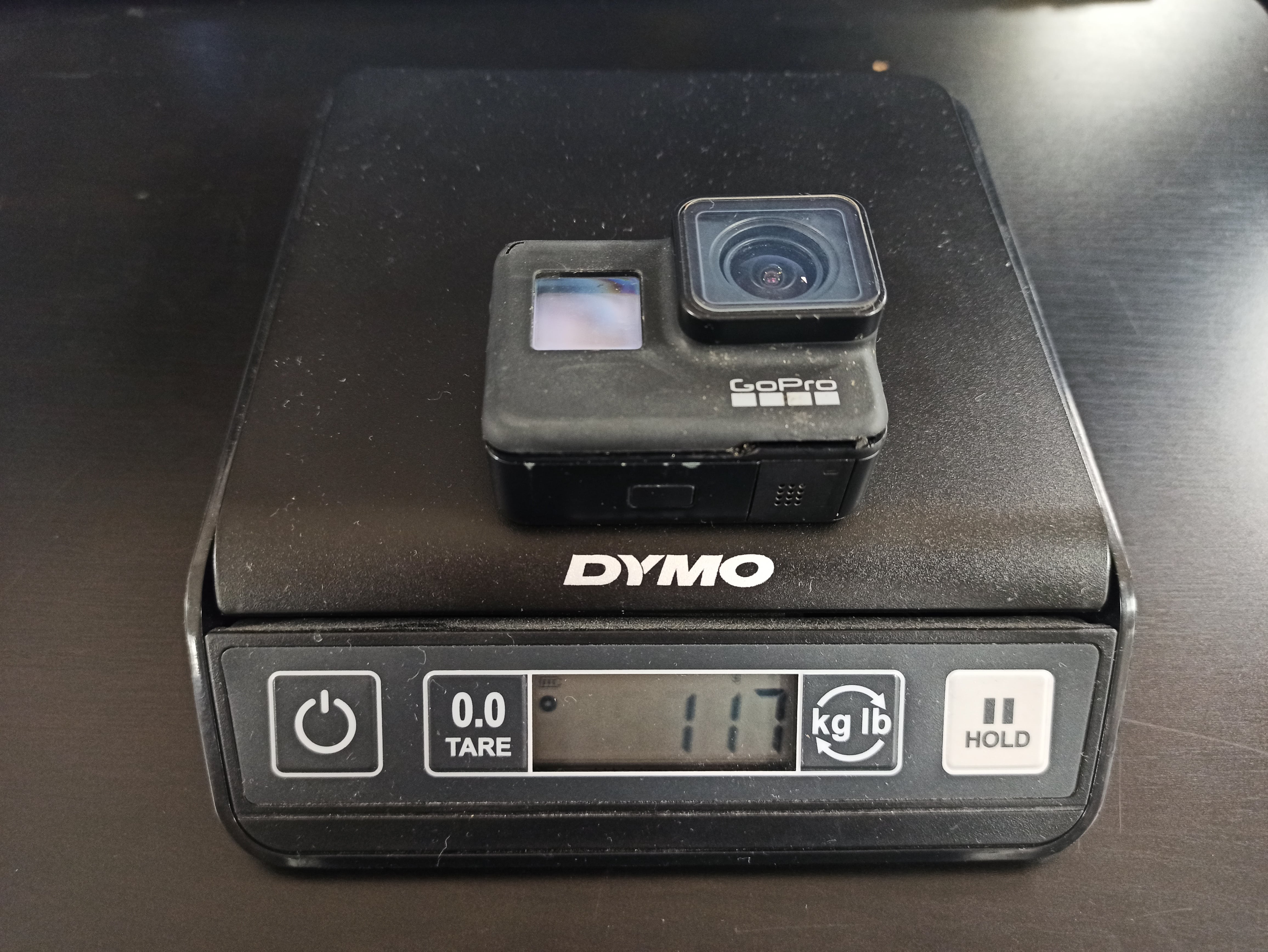
On the scales, they reached 680g of thrust, which considering an All Up Weight of 226g gives us a thrust to weight ratio of just over 3.
That ratio is probably closer to 4 in reality since I decided not to reach full throttle, seeing my wobbly cardboard stand flex and the drone move towards the edge of the scales...
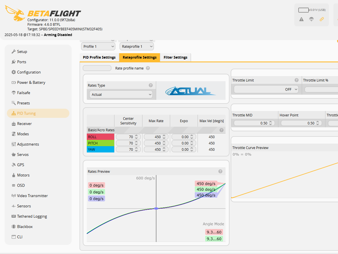
Firmware
The Flight Controller is running the open source Betaflight 4.6 firmware at the moment.
This allows me to configure anything I need such as assigning channels from the radio controller to different controls and presets,
or tune the PID loop, max rates, remap motor placement and direction, ...
Most of this can be done through a very user-friendly GUI but more in depth configuration can also be done through a CLI.
Decased Gopro
Why?
Why do we even need another camera? There's clearly already one on the schematic.
However, that camera serves one purpose and does a good job of it: broadcasting a live image, with all the key information, and with as little latency as possible.
In order to achieve this, some compromises must be made:
The feed has a resolution of 480p, and the quality of the image breaks down rapidly in presence of radio interference or objects obstructing the path of the radio waves.
This can result in the following breakup:
Definitely flyable, especially with some practice, but not the kind of finished product most clients would hope for.
Most FPV drones get around this by strapping a self-contained camera like a GoPro to the drone, but in our case a quick look at any of the GoPro's specs point to an obvious problem: they weigh more than half the drone. If we add a battery on top of that the drone will still be able to take off, but will weigh over 250g (a significant milestone in most countries' legislation) and more importantly, it will hover at such a high point in the throttle that the flight time is unlikely to be much more than a couple of minutes.
To get around this we can start tearing down the GoPro and removing anything that's not crucial to the recording function.
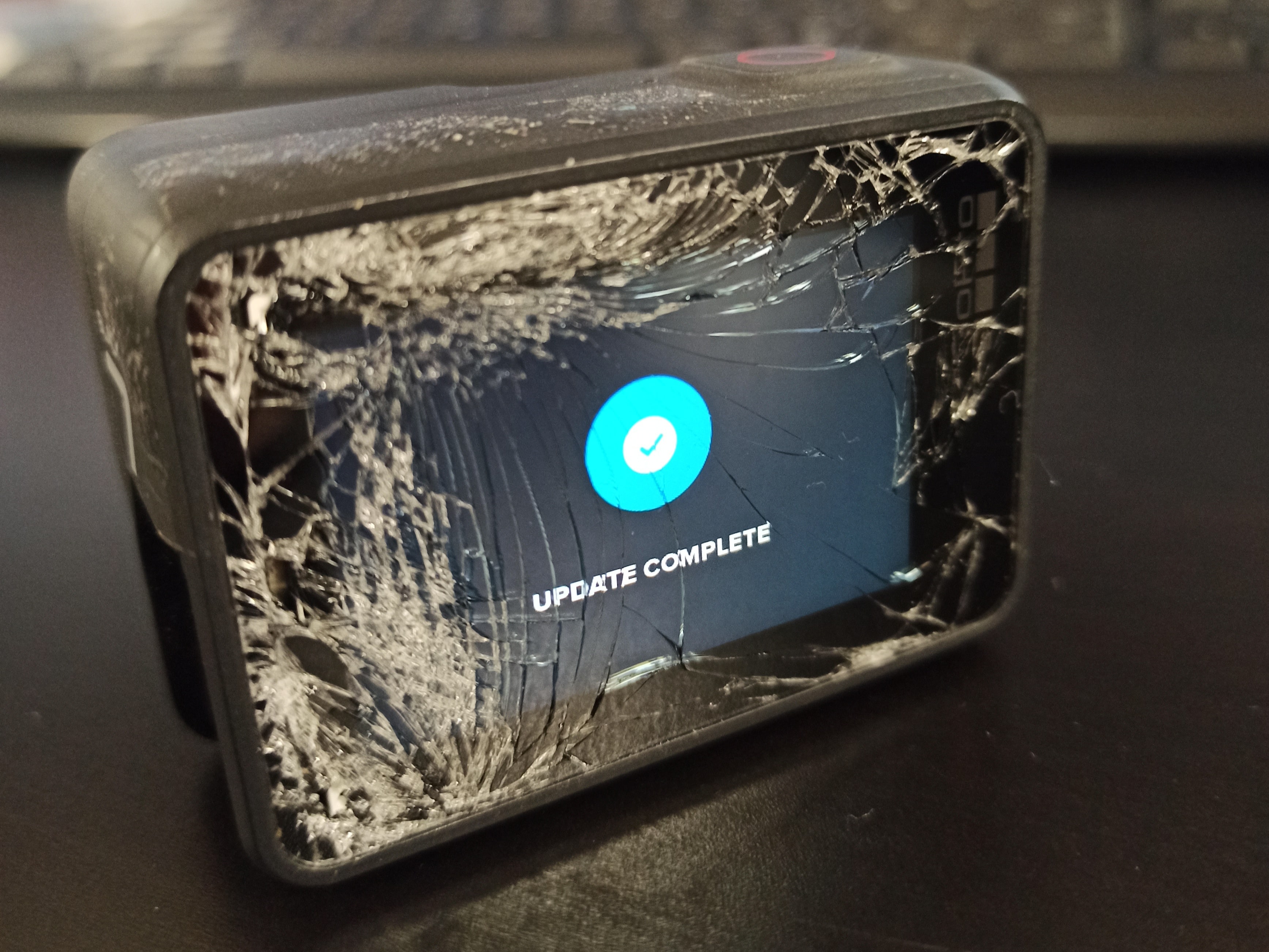
Before starting any surgical procedures, it's a good idea to flash another firmware called 'GoPro Labs' (made by GoPro) that gives us access to some functionalities most people wouldn't need. One example of this is being able to power on the camera from another power source than the provided batteries. If you've ever seen footage from a rocket launch near the boosters where the camera has had to be powered on for several hours and the recording triggered from a distance, that was probably a camera running GoPro Labs. Now for the risky part! I felt better about this given my Hero 7 Black had already seen some field (ab)use of which the rear screen is a testimony:
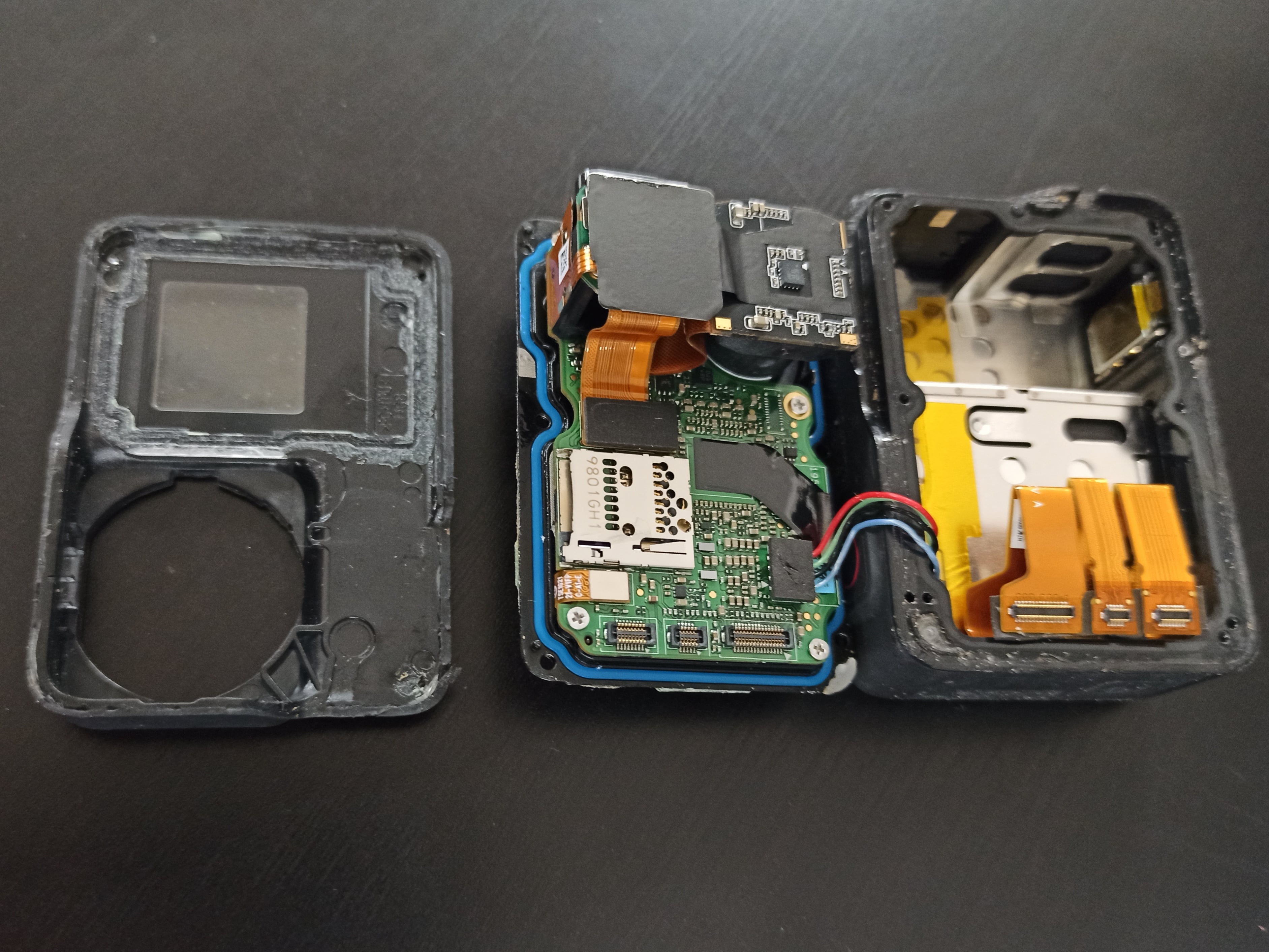
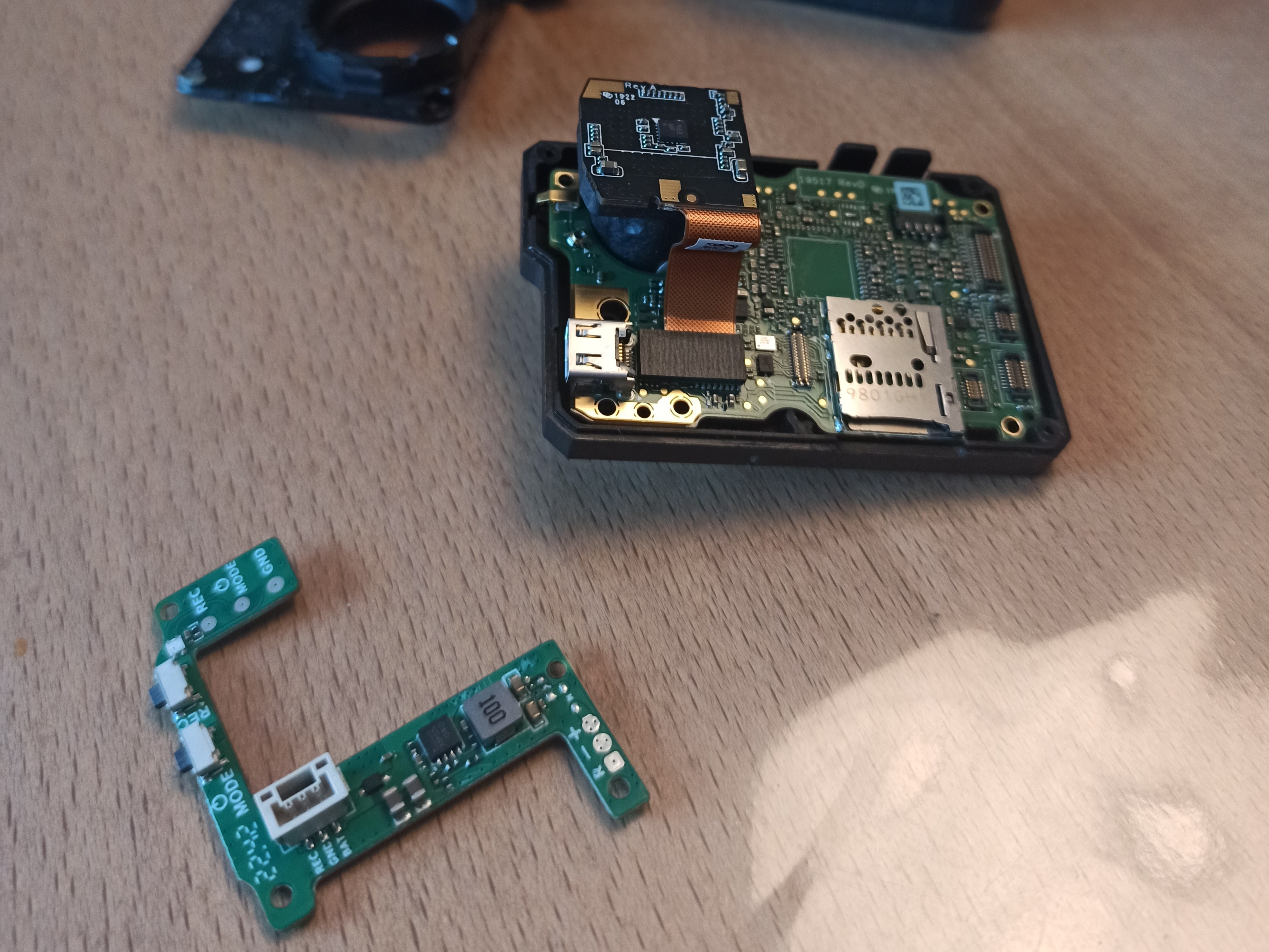
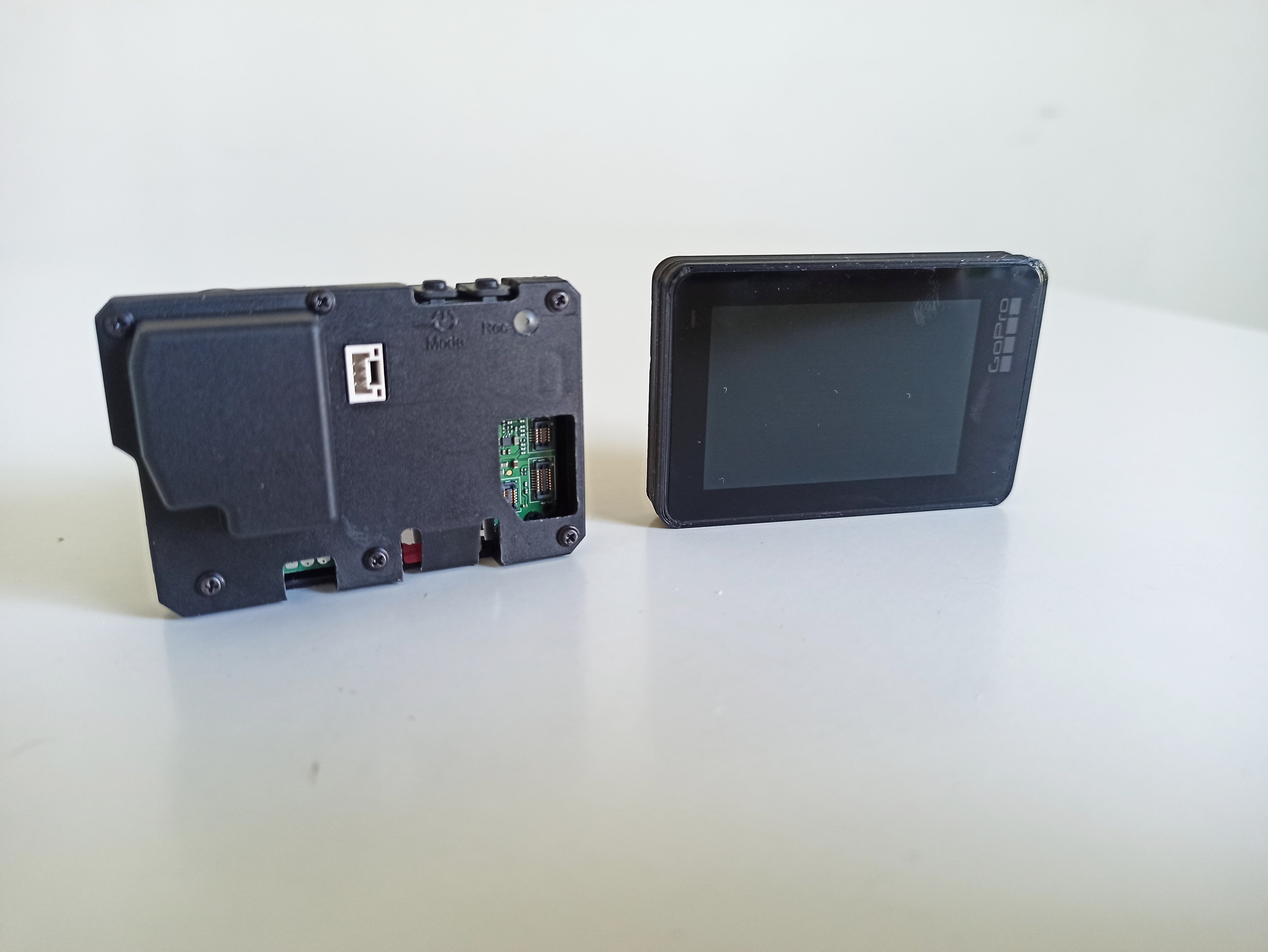
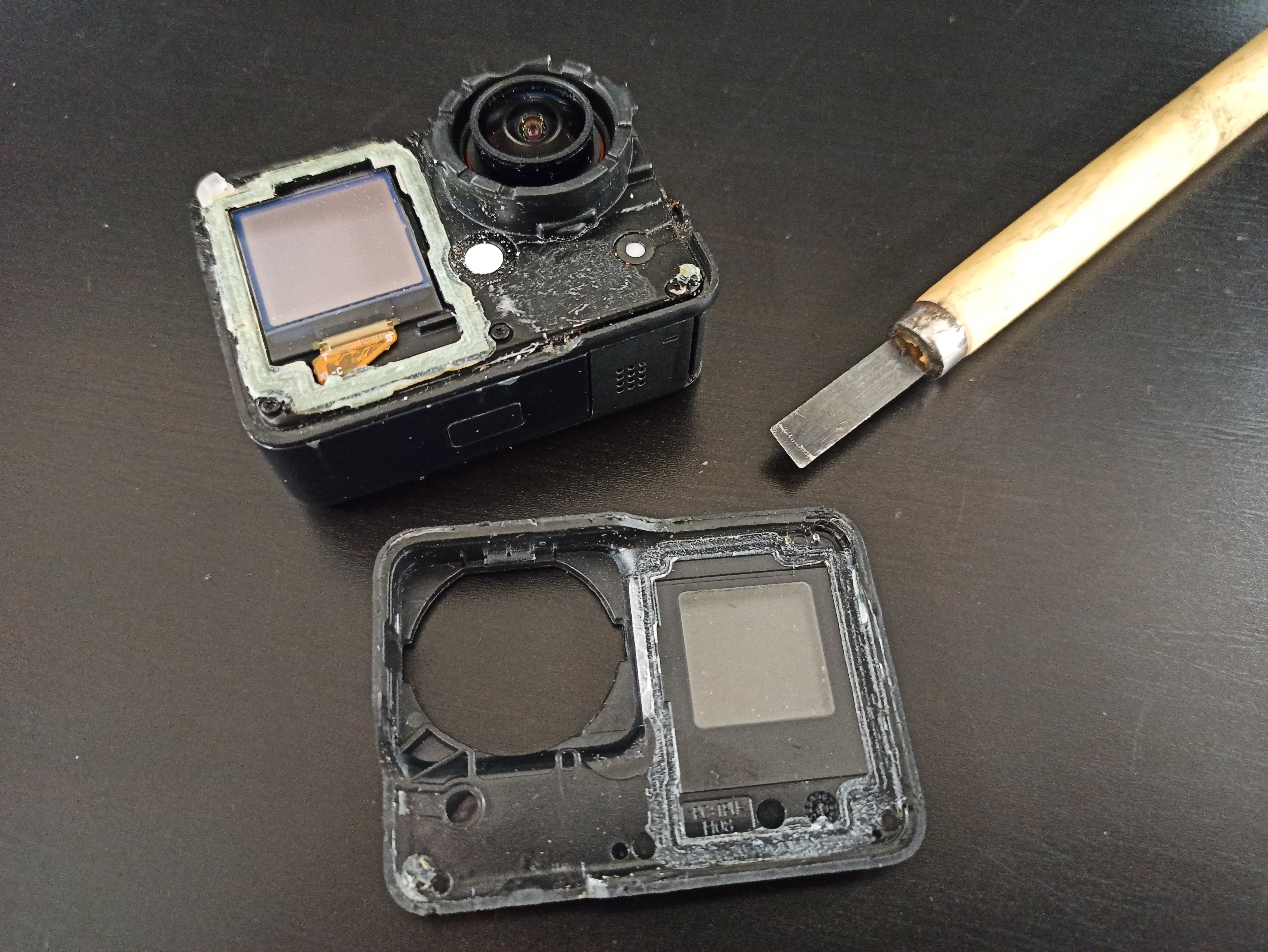
Once we've torn off the front cover, chiseled through a substantial amount of glue and removed all the screws, we're left with a main board and a sensor and lens module with a ribbon cable. All the ports (USB, HDMI, ...) can be discarded. Before adding the BEC and screwing everything into the new case, we need to solder on a new antenna for the Bluetooth/Wi-fi transmitter to prevent it from frying itself when we next power it on. Nothing fancy, just a piece of wire tuned to the right length will do. There we go! We've successfully shaved off almost 80% of the camera's weight!
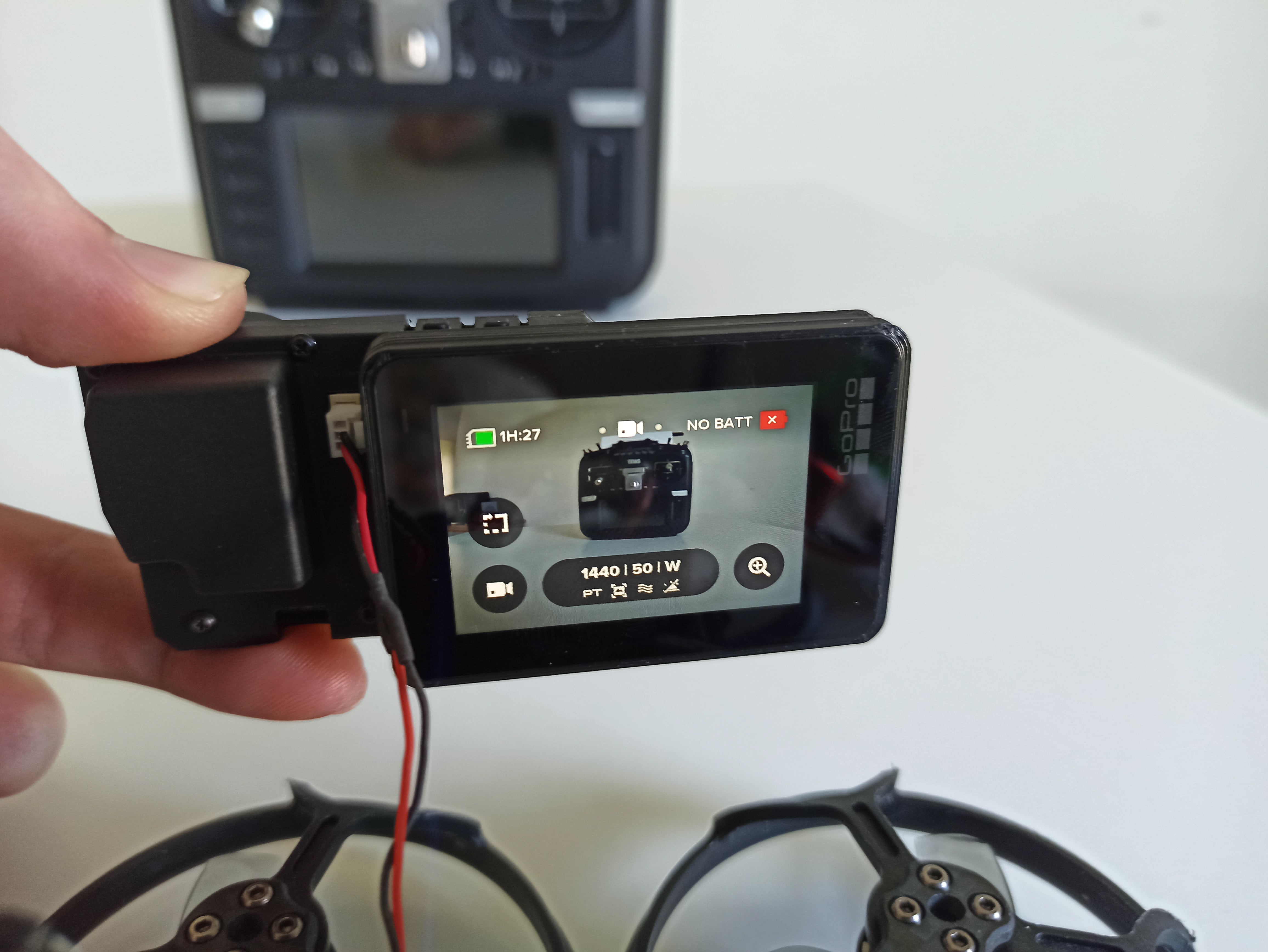
Now if we want to change the settings we can clip on this new screen in a 3D printed case allowing us to both see the live feed (used for setting exposure for instance) and also use the touchscreen to interact with the menus.
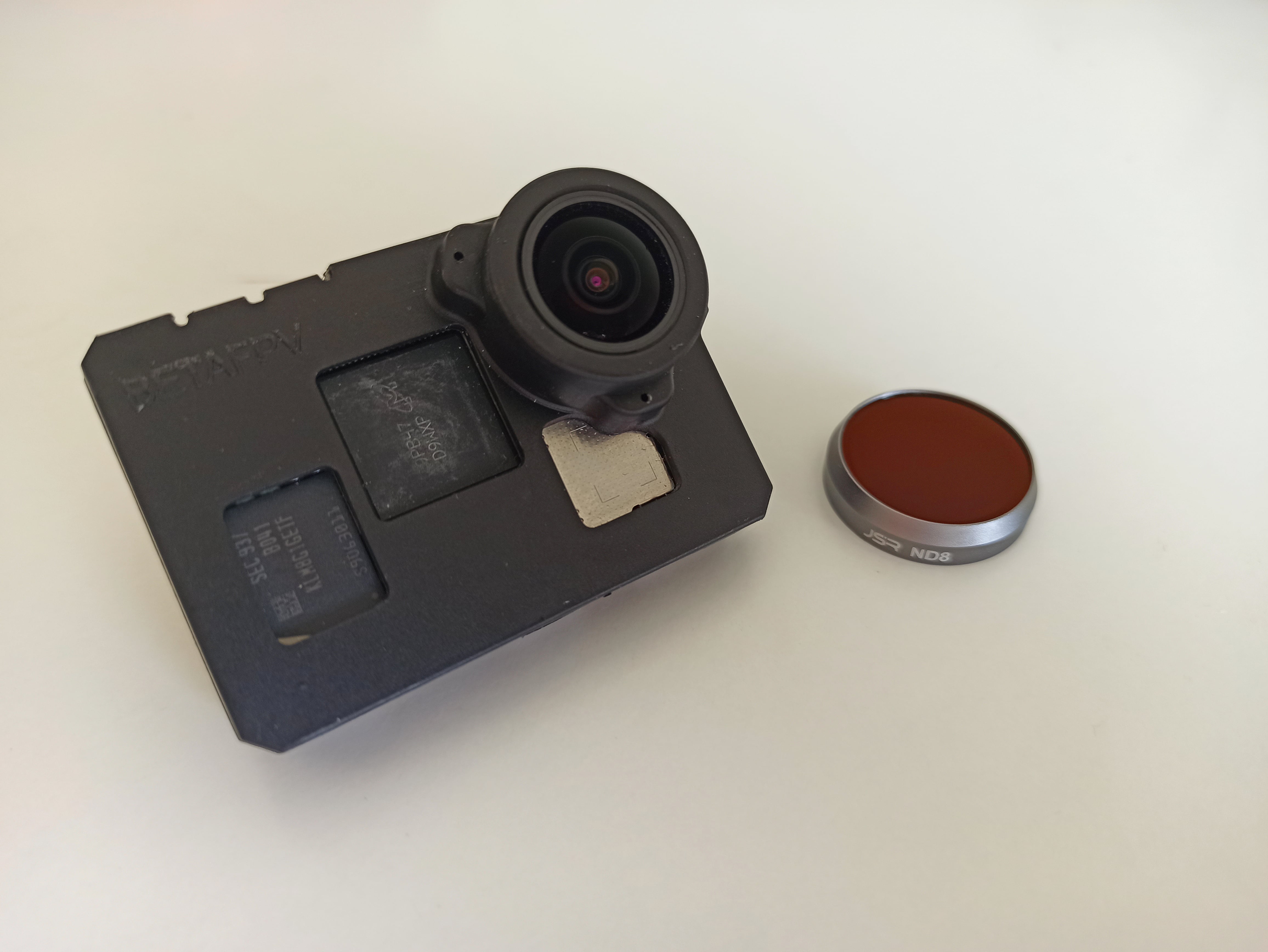
Another advantage is how the case adapts the lens to the same diameter as the Mavic Pro's camera. That drone came out back in 2016 and was popular but now completely outdated. All the third party ND filters however are still readily available, and have dropped significantly in price. These allow us to get nice motion blur around objects close by as well as protecting the lens.

Definitely flyable, especially with some practice, but not the kind of finished product most clients would hope for.
Most FPV drones get around this by strapping a self-contained camera like a GoPro to the drone, but in our case a quick look at any of the GoPro's specs point to an obvious problem: they weigh more than half the drone. If we add a battery on top of that the drone will still be able to take off, but will weigh over 250g (a significant milestone in most countries' legislation) and more importantly, it will hover at such a high point in the throttle that the flight time is unlikely to be much more than a couple of minutes.
To get around this we can start tearing down the GoPro and removing anything that's not crucial to the recording function.
Before starting any surgical procedures, it's a good idea to flash another firmware called 'GoPro Labs' (made by GoPro) that gives us access to some functionalities most people wouldn't need. One example of this is being able to power on the camera from another power source than the provided batteries. If you've ever seen footage from a rocket launch near the boosters where the camera has had to be powered on for several hours and the recording triggered from a distance, that was probably a camera running GoPro Labs. Now for the risky part! I felt better about this given my Hero 7 Black had already seen some field (ab)use of which the rear screen is a testimony:
- Most of the weight comes from the case, very rugged but this shouldn't see many crashes. We can replace it with a much thinner shell.
- The next heaviest part is the battery, We can get rid of it if we power it via the drone's battery, although this does mean adding a bec to avoid frying the logic board.
- The front and rear screens can go too. The rear screen is needed for changing settings but I'll get back to that.
Once we've torn off the front cover, chiseled through a substantial amount of glue and removed all the screws, we're left with a main board and a sensor and lens module with a ribbon cable. All the ports (USB, HDMI, ...) can be discarded. Before adding the BEC and screwing everything into the new case, we need to solder on a new antenna for the Bluetooth/Wi-fi transmitter to prevent it from frying itself when we next power it on. Nothing fancy, just a piece of wire tuned to the right length will do. There we go! We've successfully shaved off almost 80% of the camera's weight!
Now if we want to change the settings we can clip on this new screen in a 3D printed case allowing us to both see the live feed (used for setting exposure for instance) and also use the touchscreen to interact with the menus.
Another advantage is how the case adapts the lens to the same diameter as the Mavic Pro's camera. That drone came out back in 2016 and was popular but now completely outdated. All the third party ND filters however are still readily available, and have dropped significantly in price. These allow us to get nice motion blur around objects close by as well as protecting the lens.
Head Tracking Tilt
A Quick Bit of Theory
Let's quickly go over how drones move in order to understand the problem we're about to solve:
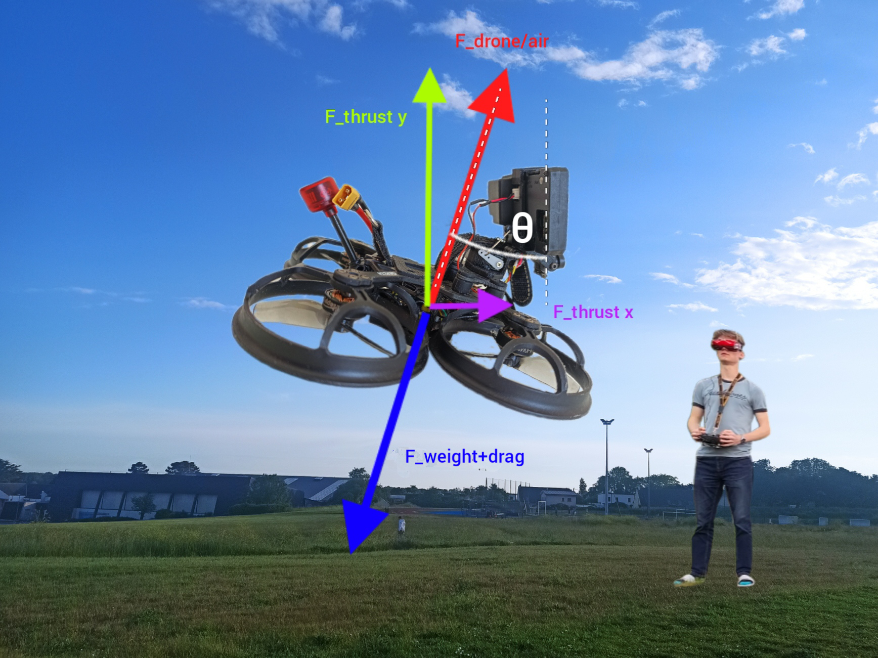 The image above sums up most of the forces that come into play when a drone is traveling forwards.
In the context of a hover, there are only really two forces: the force the drone exerts on the surrounding air,
and the reaction that air has on the drone according to Newton's third law of motion.
Pushing down on the air allows the drone to overcome gravity and stay airborne (as in the case of any heavier-than-air aircraft).
If we want to move the drone on any other axis than the vertical one however, we need to strategically tilt the drone as seen in the magnificent illustration above.
Now the vertical component of the reaction (in green) keeps the drone in the air, whilst the horizontal component (in purple) serves for direction.
The image above sums up most of the forces that come into play when a drone is traveling forwards.
In the context of a hover, there are only really two forces: the force the drone exerts on the surrounding air,
and the reaction that air has on the drone according to Newton's third law of motion.
Pushing down on the air allows the drone to overcome gravity and stay airborne (as in the case of any heavier-than-air aircraft).
If we want to move the drone on any other axis than the vertical one however, we need to strategically tilt the drone as seen in the magnificent illustration above.
Now the vertical component of the reaction (in green) keeps the drone in the air, whilst the horizontal component (in purple) serves for direction.
However, what if we want to film something whilst moving backwards? The drone tilts backwards, so does the camera, and now it's looking straight at the sky... In a similar way, if we want to pan down to track or reveal a subject, a static tilt will result in a sudden violent forwards acceleration whether desired or not.
Now we understand why having a variable tilt can be such a game changer, and I recommend you go back and watch that first video and try to make out when the camera tilt is changing. The CAD animation below shows how simple that can be. As long as both the pilot's feed camera and the main camera both tilt together, all it takes are a couple of 3D printed parts and a servo motor.
A Simple Four Bar Linkage
Now that we've established that a multirotor must tilt to move around, it becomes obvious why FPV drones add a tilt to their camera (theta in white here):
the up-tilt prevents them from looking down at the ground when moving forwards.
The faster the drone plans on flying, the more aggressively it tilts forwards and the more up-tilt becomes necessary.
However, what if we want to film something whilst moving backwards? The drone tilts backwards, so does the camera, and now it's looking straight at the sky... In a similar way, if we want to pan down to track or reveal a subject, a static tilt will result in a sudden violent forwards acceleration whether desired or not.
Now we understand why having a variable tilt can be such a game changer, and I recommend you go back and watch that first video and try to make out when the camera tilt is changing. The CAD animation below shows how simple that can be. As long as both the pilot's feed camera and the main camera both tilt together, all it takes are a couple of 3D printed parts and a servo motor.
The linkage is made from a piece of paperclip, the thought being that this would be the first point of failure in a crash to prevent anything more precious from being damaged.
Initially this didn't go to plan since I tried saving weight by choosing a plastic gear servo.
The first small crash was enough to shear off some of the teeth inside, but since switching to metal gears that's no longer a problem.
Now all we need is both a way to send tilt controls to the drone, and a way to control the servo, both have pretty neat solutions:
There we go, put that all together and we have a functioning head tracking drone capable of some pretty impressive shots.
I would recommend this project or something similar for the multidisciplinary aspect of it. I think it's a good display of use of electronics, mechanical design, and overall problem solving with some embedded systems notions sprinkled in.
Now all we need is both a way to send tilt controls to the drone, and a way to control the servo, both have pretty neat solutions:
- With both hands on the controller, adding the tilt to a potentiometer on the remote isn't a viable option. However most radios have a port on the top that allows for a second controller to be plugged in. The main use case is having both a student and instructor in control of the same plane, with the instructor having higher priority. What's actually happening is the information from the second controller gets added to more channels sent to the aircraft on top of those from the first radio. The goggles can therefore emulate the second radio by sending 3-axis Euler angles over PPM. This isn't perfect as it drifts over time and my goggles must be defective since all axis are mixed (i.e. looking left will also make the pitch axis respond) It stays usable for this application but I have some ideas on implementing my own headtracker in the future that could solve this.
-
Moving the servo takes some creativity since the flight controller doesn't have any dedicated servo outputs as would a fixed-wing FC.
However, it does have an RGB LED signal pad that outputs PWM in order to change the colour of LED strips during drone races to tell apart pilots.
In order for the servo to move when the pilot tilts their head, we can simply remap the RGB signal pad to mirror the channel on which we're sending the head tracker data.
This can be done via the CLI with the following commands:
- "resource list" displays the pads currently assigned to the F405's timers for PWM usage, this includes the motor outputs
- say we see the led pad on pin A9. We can remap A9 to an abstract object called 'servo': "resource servo (servo number) A9"
- Finally we can finish off with
"servo (servo number) (min_value) (max_value) (mid_point) (rate) (direction)"
to set up the servo, and
"smix (servo_number) (aux_channel) (scale_min) (scale_max) (offset)"
to assign the servo to a channel of our choosing
There we go, put that all together and we have a functioning head tracking drone capable of some pretty impressive shots.
I would recommend this project or something similar for the multidisciplinary aspect of it. I think it's a good display of use of electronics, mechanical design, and overall problem solving with some embedded systems notions sprinkled in.
Thank you for reading this far.
If you would like any information, CAD or config files feel free to ask. I wish you the same satisfaction of making something you're proud of, and that allows you to experience the joy of flight in exploring God's creation.
In the words of Leonardo Da Vinci: "Once you have tasted flight, you will forever walk the earth with your eyes turned skyward, for there you have been, and there you will always long to return."