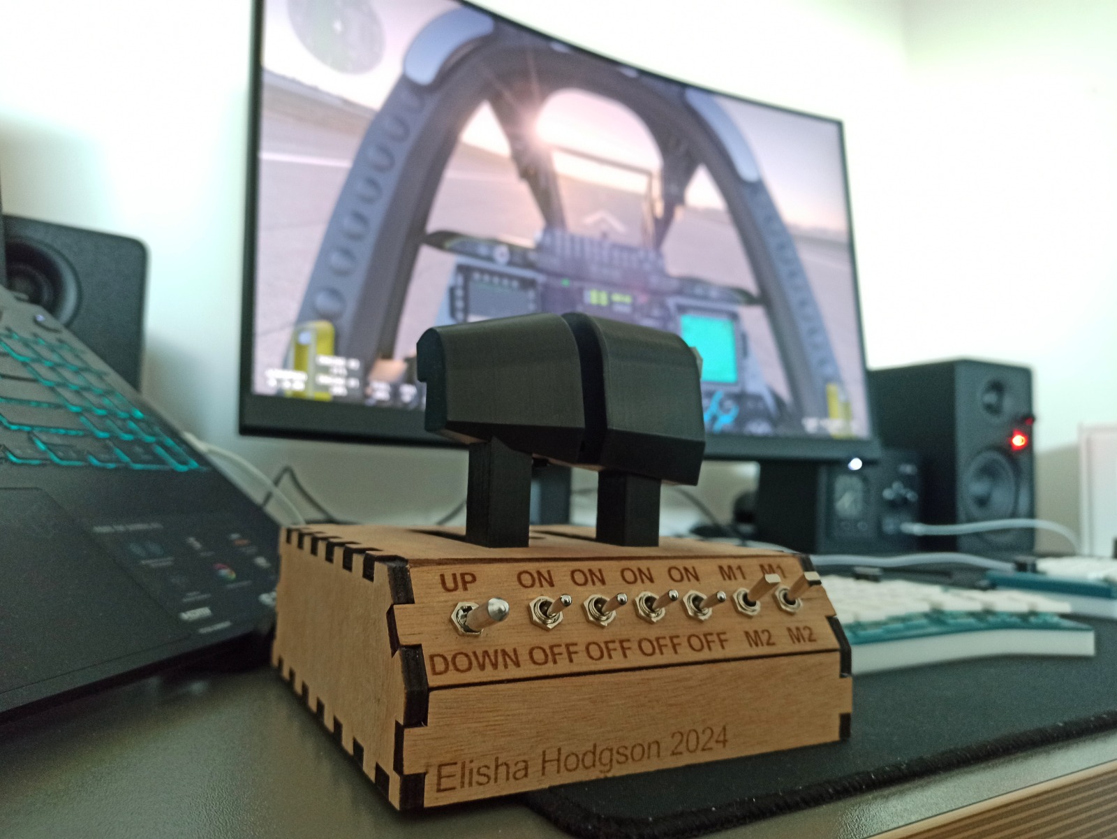
A cockpit in a shoebox
Student Stick is a full flight sim cockpit providing an immersive and realistic experience for flying virtual planes and rotorcraft
in simulators such as Microsoft Flight Simulator or Xplanes.
It solves the fairly niche challenge of an aviation enthusiast student:
These were my requirements:
This project showcases some creative hardware design and integration, it was completed in 3-4 months in the free time around my lectures.
These were my requirements:
- As compact as possible, must fit in a shoebox in order to fit in my 16m² dorm.
- Despite this it must still comprise of a full-sized flight stick, set of rudder pedals and multi-engine throttle/rotorcraft collective.
- Finally the total cost must be student-friendly.
This project showcases some creative hardware design and integration, it was completed in 3-4 months in the free time around my lectures.
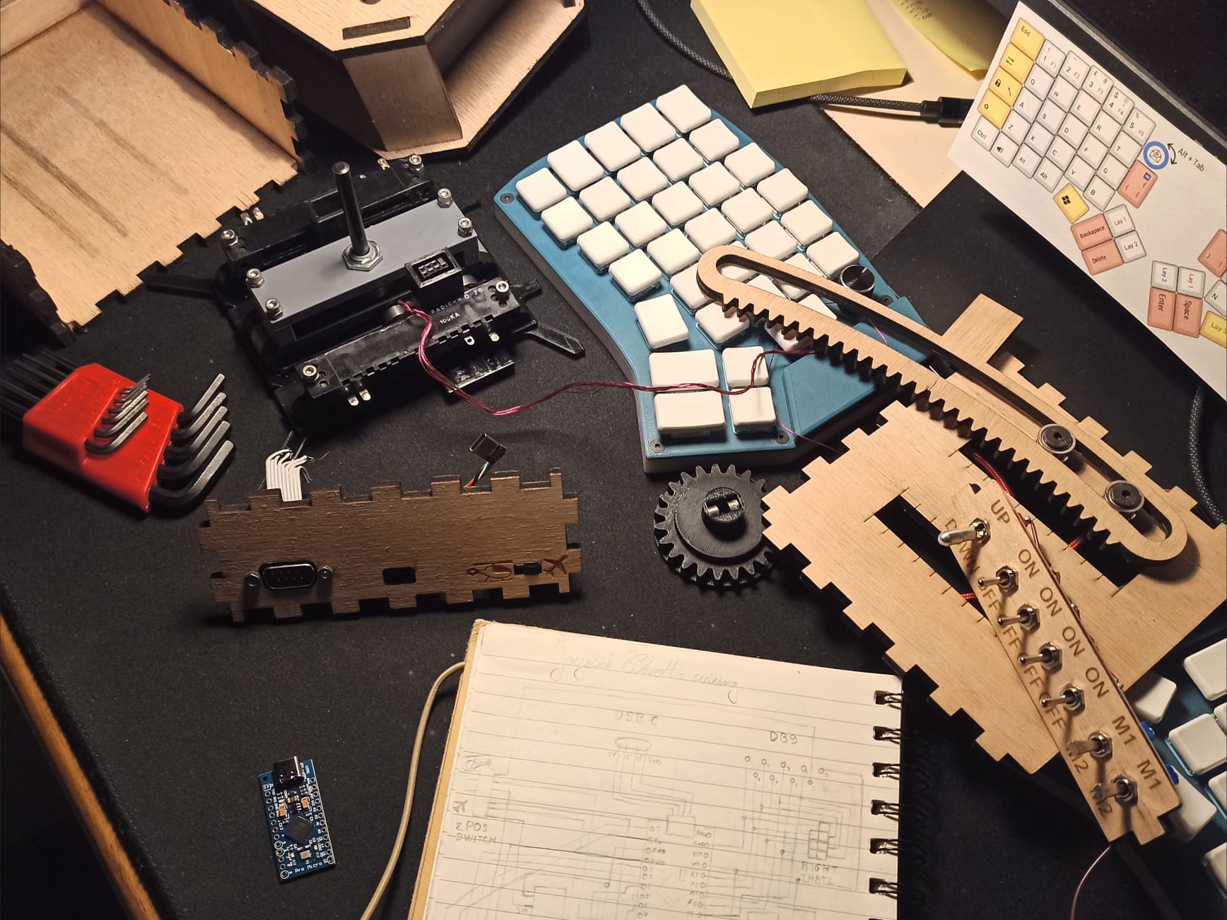
This project page is split into sections breaking down each of the subsystems that make up the cockpit.
The titles in the following table of contents are clickable shortcuts to take you to their respective segments:
The titles in the following table of contents are clickable shortcuts to take you to their respective segments:
Rudder Pedals
Design
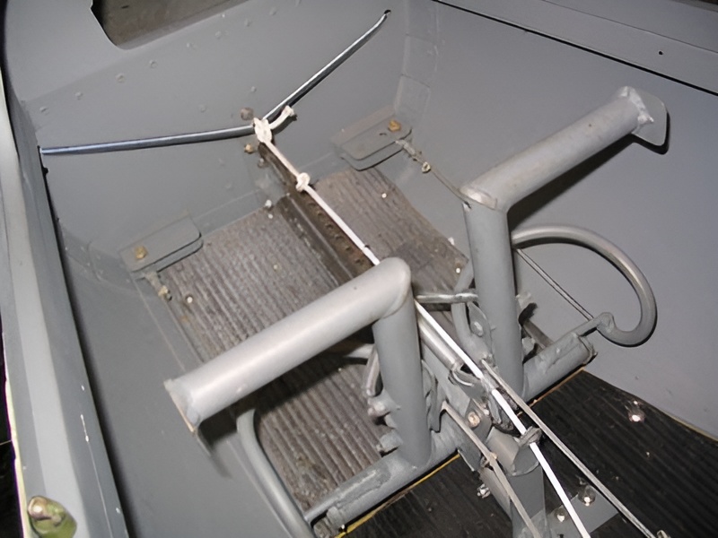
The design I was going for was one similar to that of the rudder pedals of a small bush plane:
The detail in the terrain on recent simulators results in me choosing aircraft like the Savage Cub over anything else. These pedals (also found on most gliders and rotorcraft) only pivot back and forth, unlike larger aircraft where pushing both pedals engages the brakes.
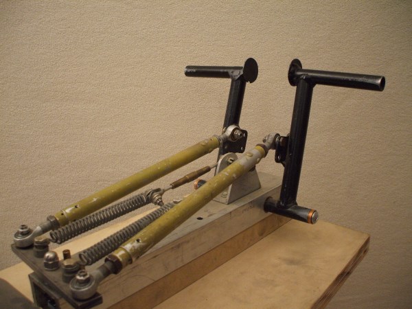
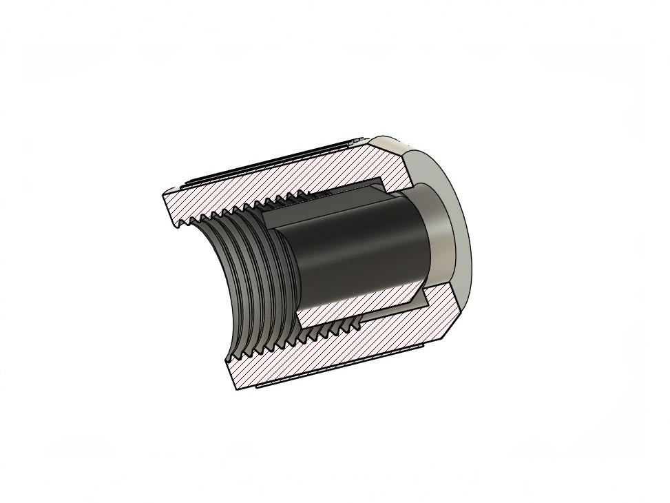
When one side is pressed, the other rises accordingly. This motion is usually achieved with either a hydraulic system (1st image) or mechanical ball linkages (2nd image).
Despite being robust and reliable, both of these options are relatively costly and come with a large footprint.
Toe-Pivot Rudder Pedals
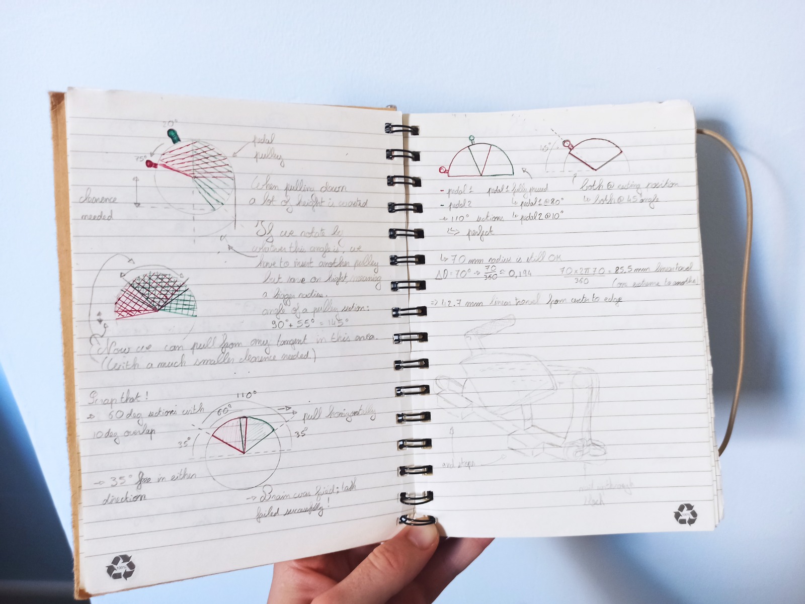
I instead opted for a set of pulleys, connected by a piece of cord that is pulled back and forth. The pulleys are sized such that each pedal has a 70° range of motion (±35°). The pedal position is measured via a Hall effect sensor: a part holding two magnets in different orientations is rotated by the moving cord to present either the North or South pole towards the sensor. This changes the voltage on its signal output which can be read by a microcontroller and converted to an analog input of a USB peripheral that can be interpreted by the computer.
Construction
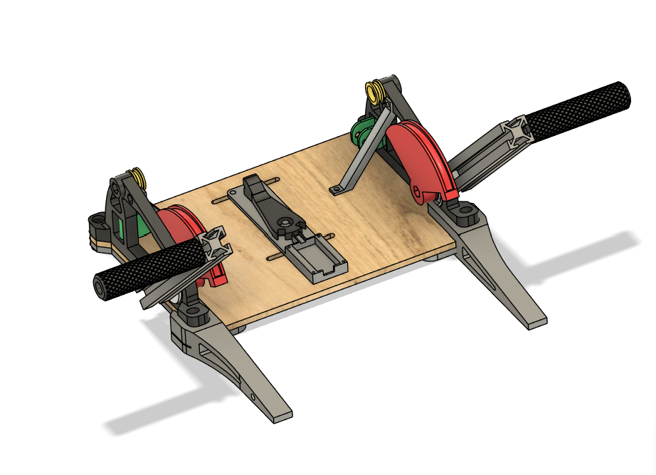
This entire project is mainly constructed from PLA printed parts, laser-cut plywood and various sizes of ball bearings
held together by hardware ranging from M3 to M5.
Two vertical side plates make up symmetrical assemblies supporting the pedal pivots and guide pulleys. The junction of the plates and the baseplate requires braces to withstand the tension on the cord. After exiting the guide pulleys, the cord is redirected to a set of vertical pulleys free to pivot around a vertical nail as the angle of the rope coming off the magnet "finger" changes throughout the range of motion. This finger is mounted on another bearing holding it to a plate. By moving this plate left or right along the slots in the baseplate, a "trim" can be adjusted to ensure the sensor outputs a neutral value at rest. By loosening and changing the position of where the finger clamps down on the cord, the angle of the pedals can also be adjusted in order for them to be level at rest.
By using aluminium extrusion for the pedals, not only is the position of the toe-bar adjustable, but also the pedals themselves removable thanks to a dovetail profile sliding into the extrusion's slots. This ensures the pedal assembly is easily disassembled as shown in the video, greatly decreasing the overall volume taken up. The other space-saving measure is a pair of clip-on feet serving multiple purposes:
- They give the rubber bands (hopefully soon replaced by suitable springs) at an angle where they have enough leverage to return the pedals to the center position at rest
- By raising the pedals' baseplate off the floor they create clearance for the nuts below it
- Without them the pedals would tip forwards when pressed, since the pivot point is so close to the edge.
- They space the pedals from the wall against which they're propped up which would otherwise limit their range of motion.
Software
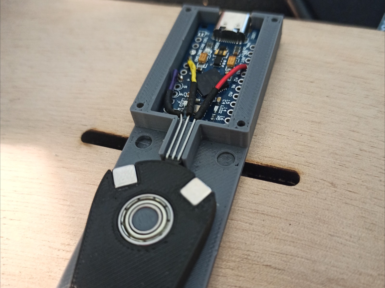
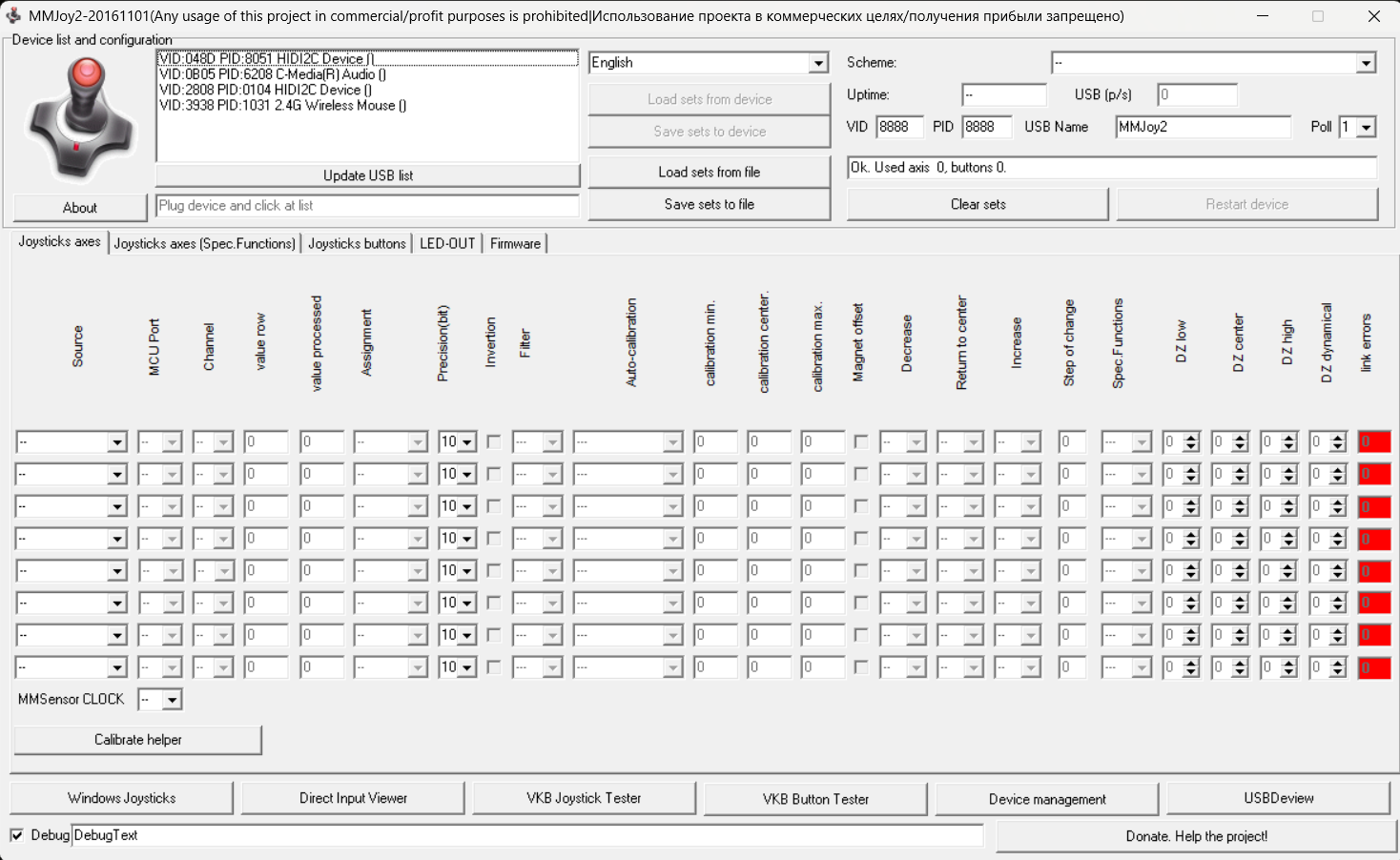
The Pedals contain a cheap USB-C Arduino Pro-Micro Clone running the MM-Joy2 OpenSource project.
The Atmega 32U4 chip's 10bit ADCs result in 1024 values, or a resolution of approximately 0.17mm between 2 values.
Plotting the output revealed the variation in magnetic field North and South Poles wasn't linear. Thankfully the MM-Joy2 configurator allows for this to be accounted for: an exponential coefficient was calculated allowing for an almost linear output of the pedal axis.
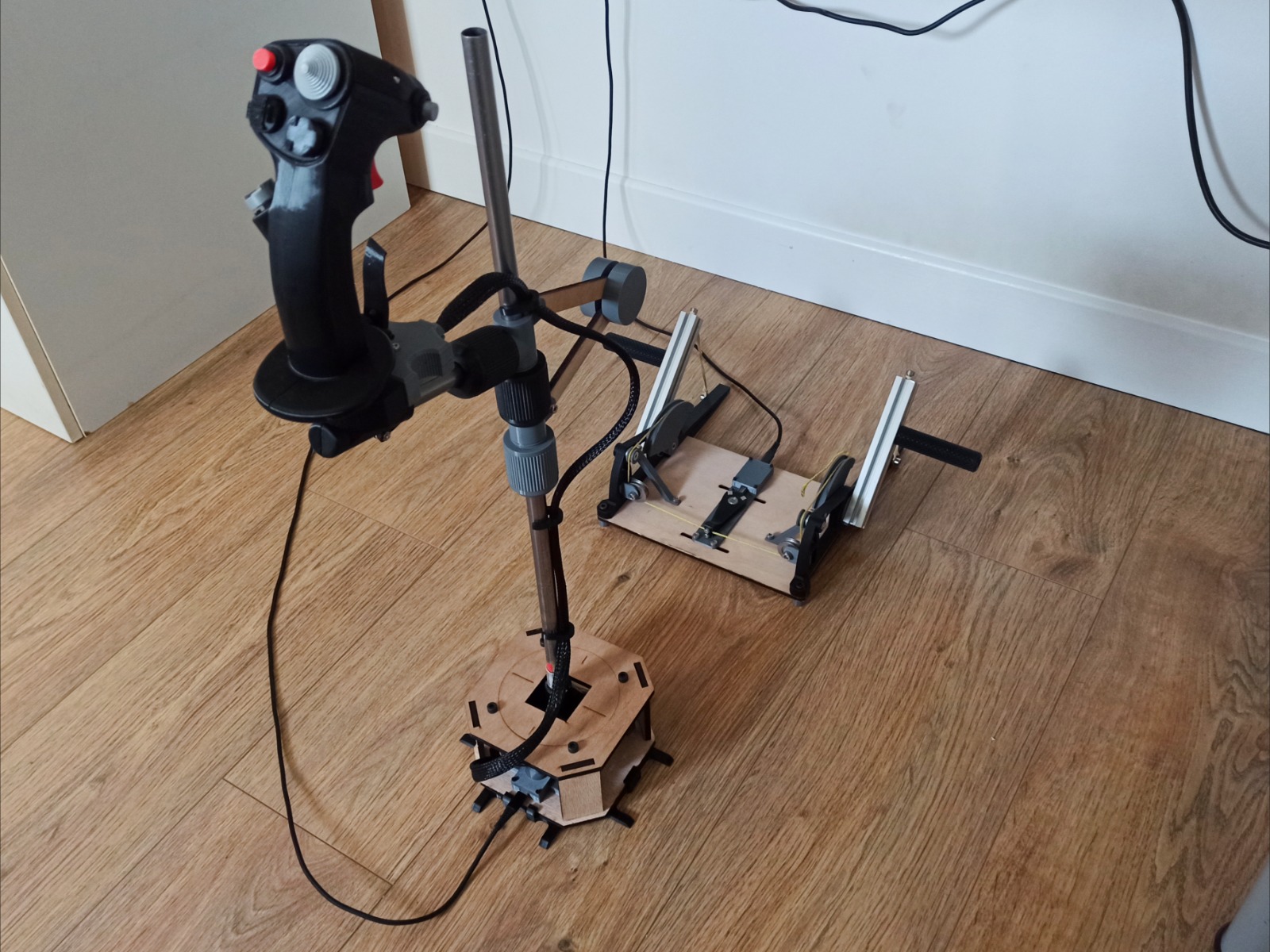
Joystick
Grip and Gimbal
The joystick is built around two tried and tested designs made available online:
The F16 sidestick grip by Spock on Printables
and the joystick gimbal by Olukelo on Thingiverse.
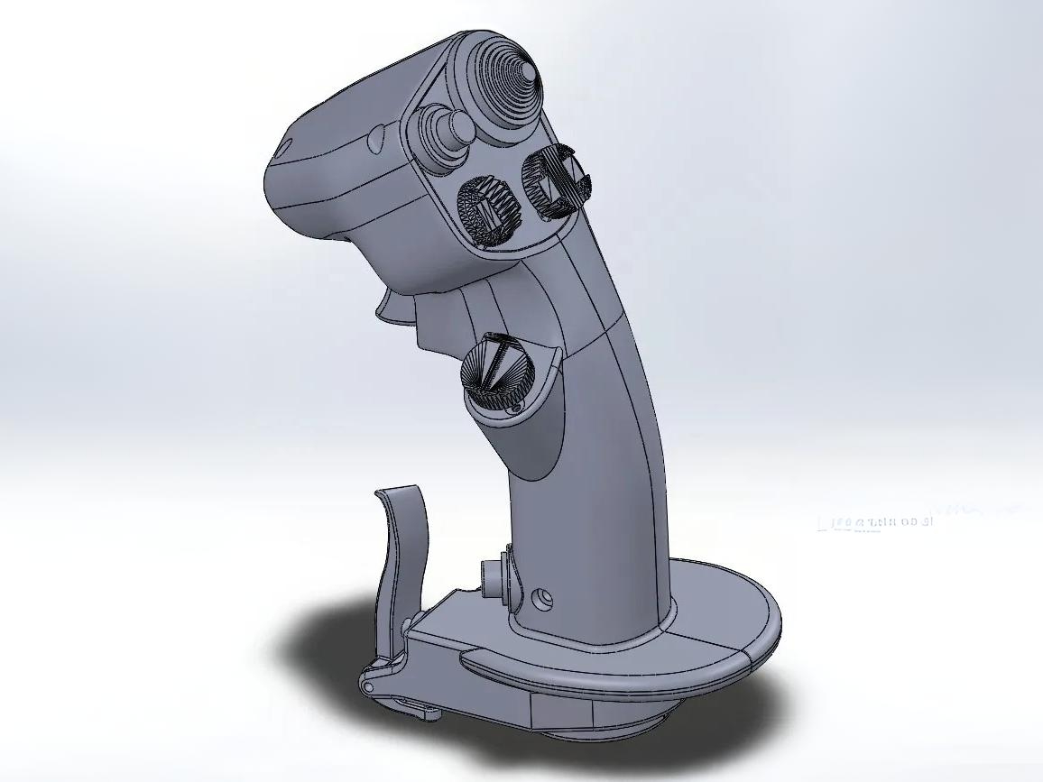
(Images from Printables and Thingiverse pages)
These subsystems prevented me from spending a significant amount of time developing that which has already been perfected by others before me.
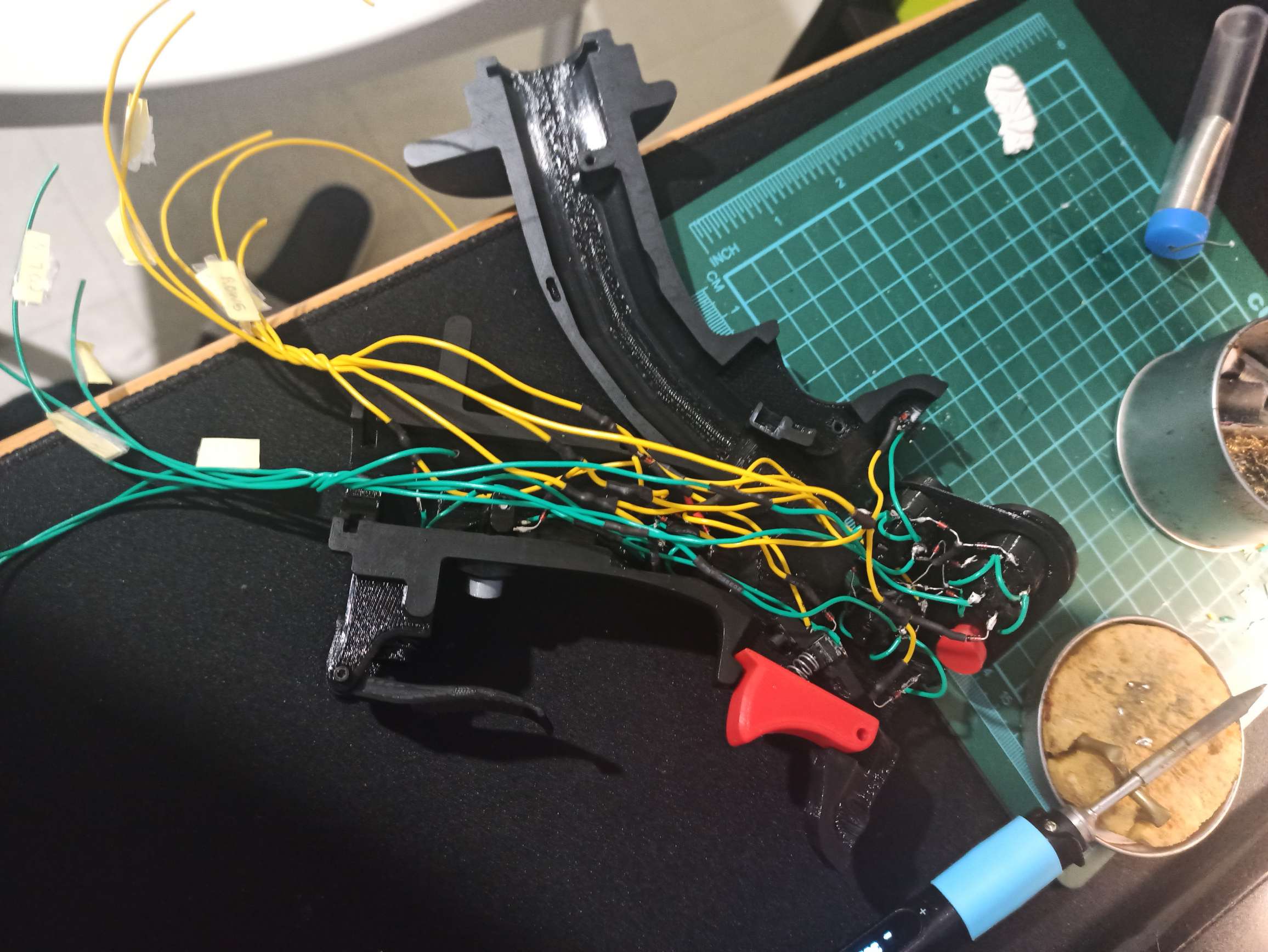
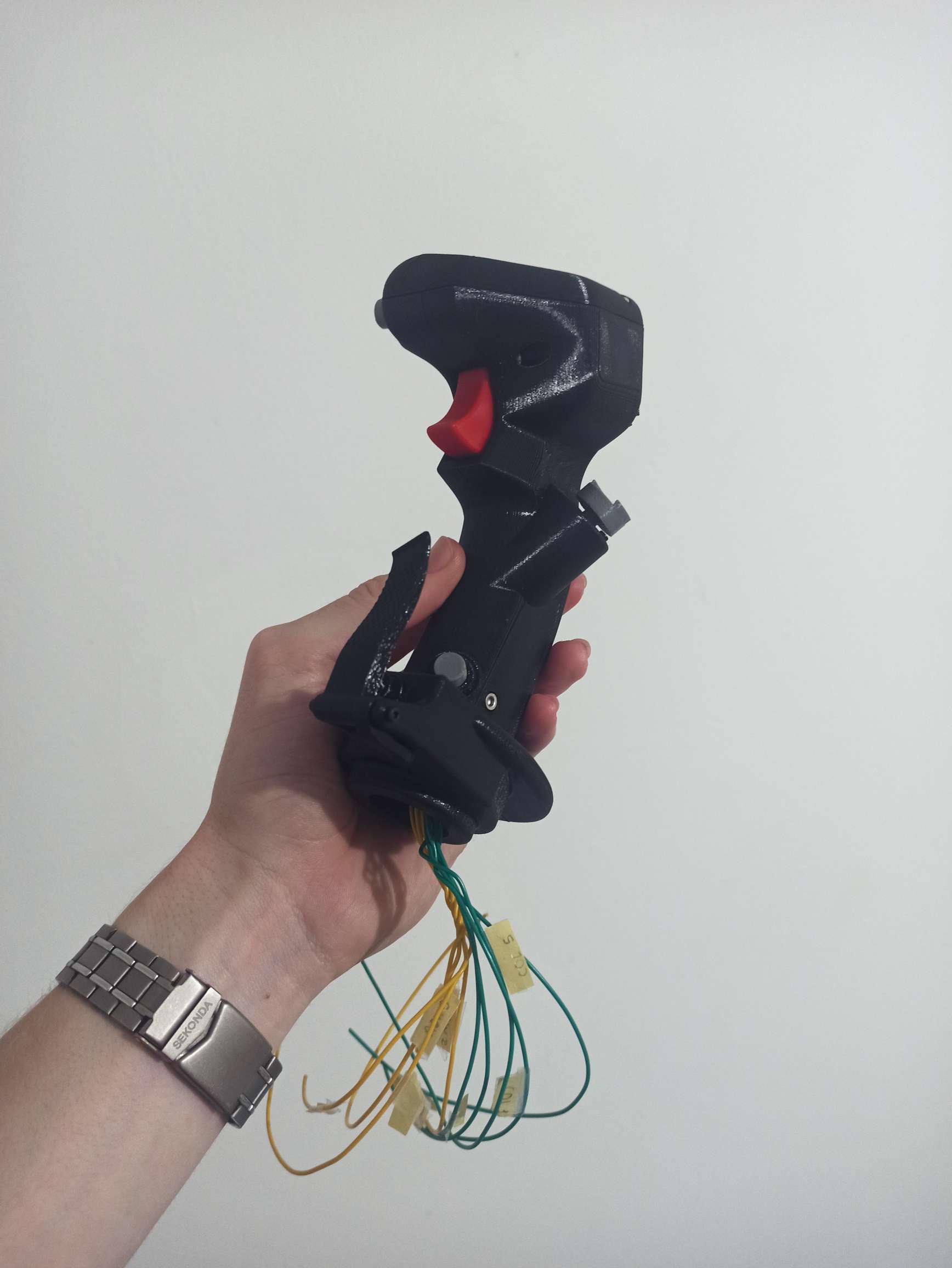
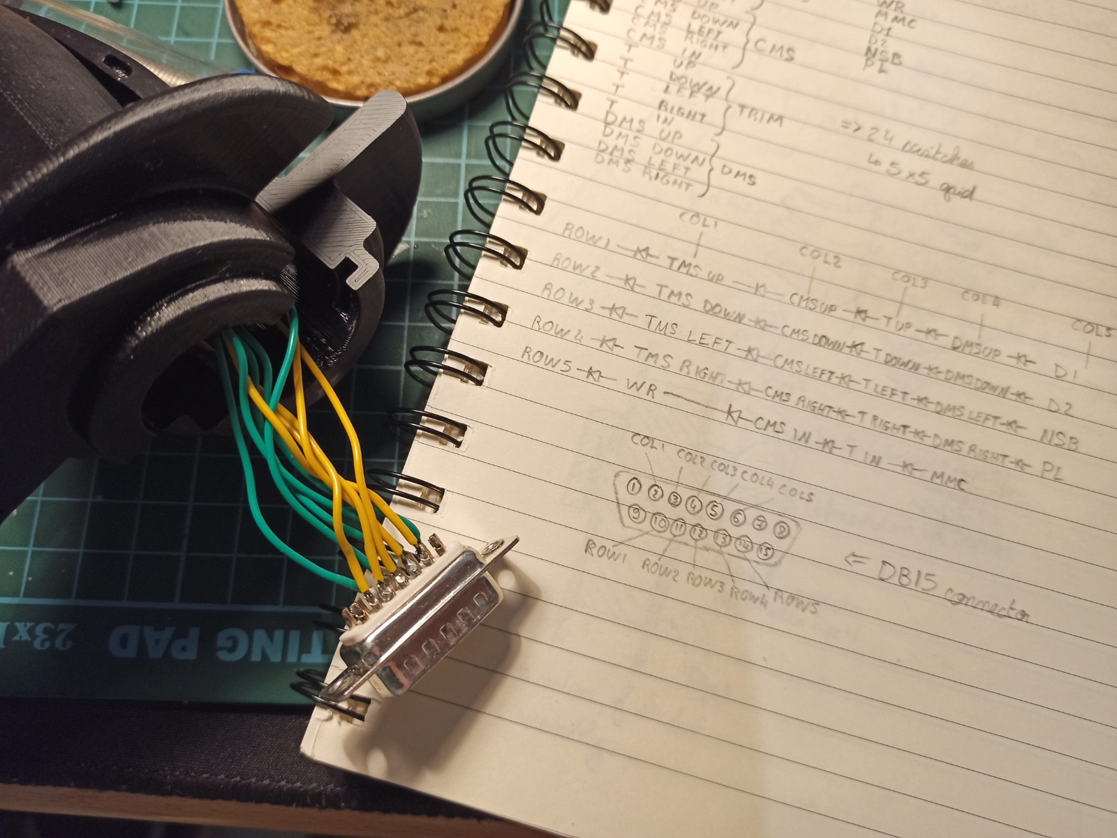
The stick grip is easily assembled using M2 hardware, and contains spaces for 24 individual 4x4mm switches. They make up 5 direction hats, a dual threshold trigger, and various other auxiliary controls.
These can be wired in a matrix alongside diodes to significantly decrease the amount of wiring (down from 24 signal + 1 ground to 5 columns and 5 rows). The diodes just prevent certain combinations of switches from causing other buttons to be read as if pressed (I've gone into more detail on the concept of switch matrices on my keyboard project page).
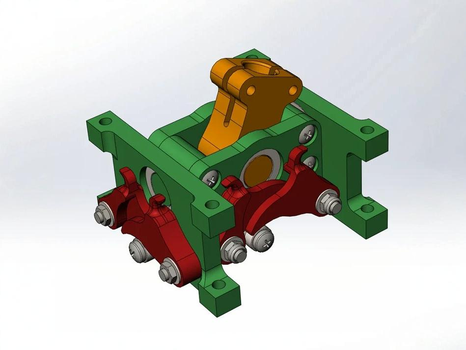
The gimbal assembly relies on bearings to ensure a smooth movement. The centering force is applied by rubber bands (until I find the right sized springs) through a dual cam setup. This allows the tension throughout the range of motion to be tailored by changing the cam profile. After modifying a few of the parts to mount sensors and facilitate cable management, I designed and laser cut a simple wooden enclosure for it to bolt into.
Adjustability
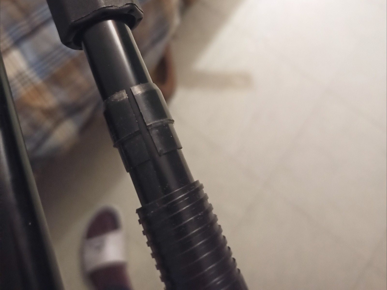
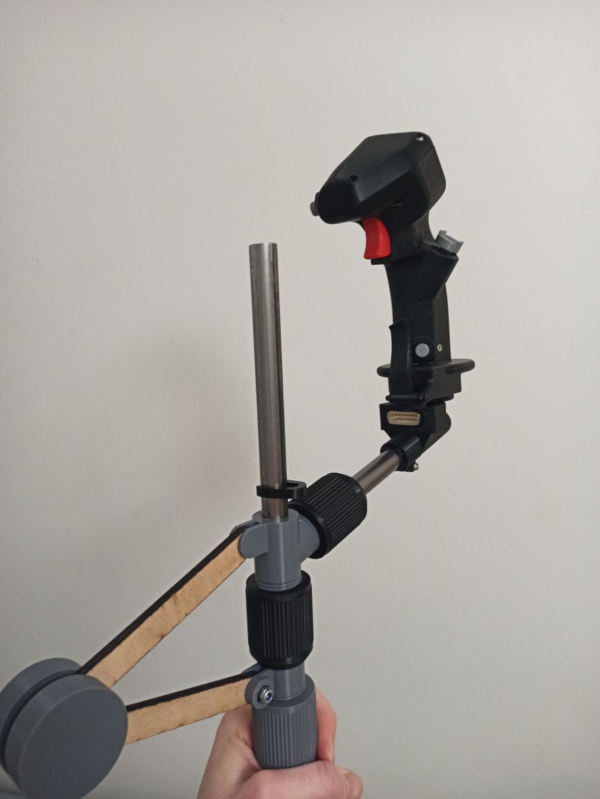
A stainless steel tube connects the gimbal and grip. It can be split into two connecting halves for storage and tipped with a metal ring to prevent twisting.
To be used with chairs of different heights, the grip needs to be adjustable.
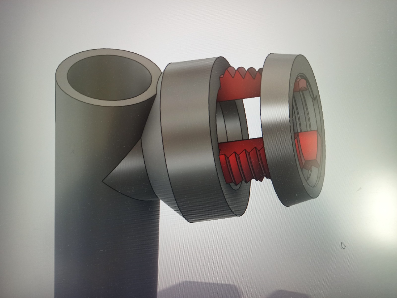
My first attempt at a pole gripping mechanism (using a conical thread) had issues jamming up.
I later came across a friend's telescopic tripod that utilised a collar whose missing section and bezel allowed for its radius to decrease to the point of preventing all relative movement with the tube around which it is placed when pressure is applied by another collar screwed up against the bezel.
The steel tube also angles back towards the chair. This allows for it to be pulled back to its full extent without coming into contact with the seat. However this offsets the center of gravity: now the stick doesn't return to the correct center position.
The fix I came up with was to add two more of the clamping mechanisms on the end of linkages connected in the center with a pivoting weight. This hollow print filled with iron filings can be placed further or closer to the stick depending on the distance between the two clamps.
The resulting leverage counteracts the offset weight and re-centers the grip.
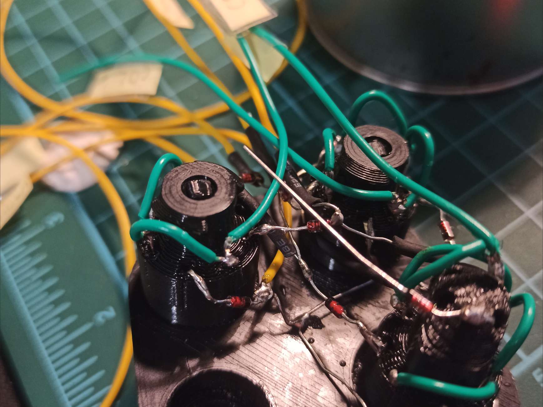
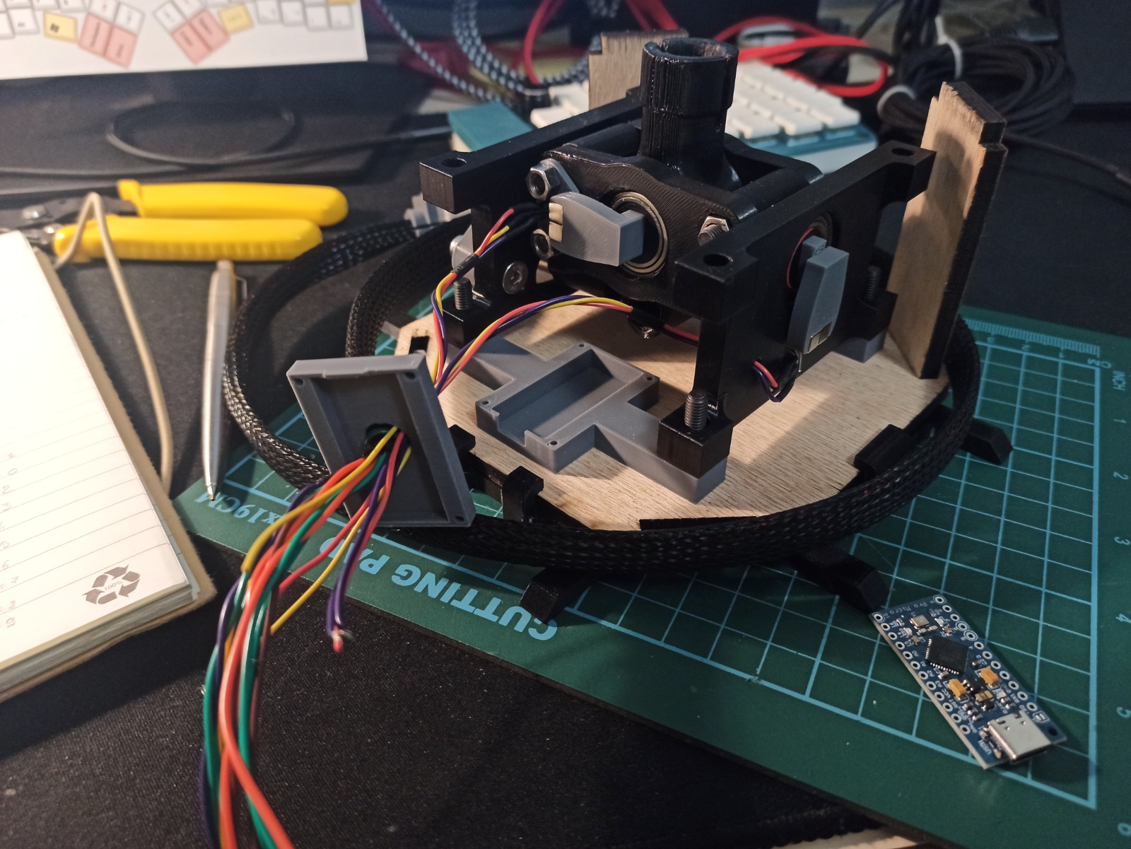
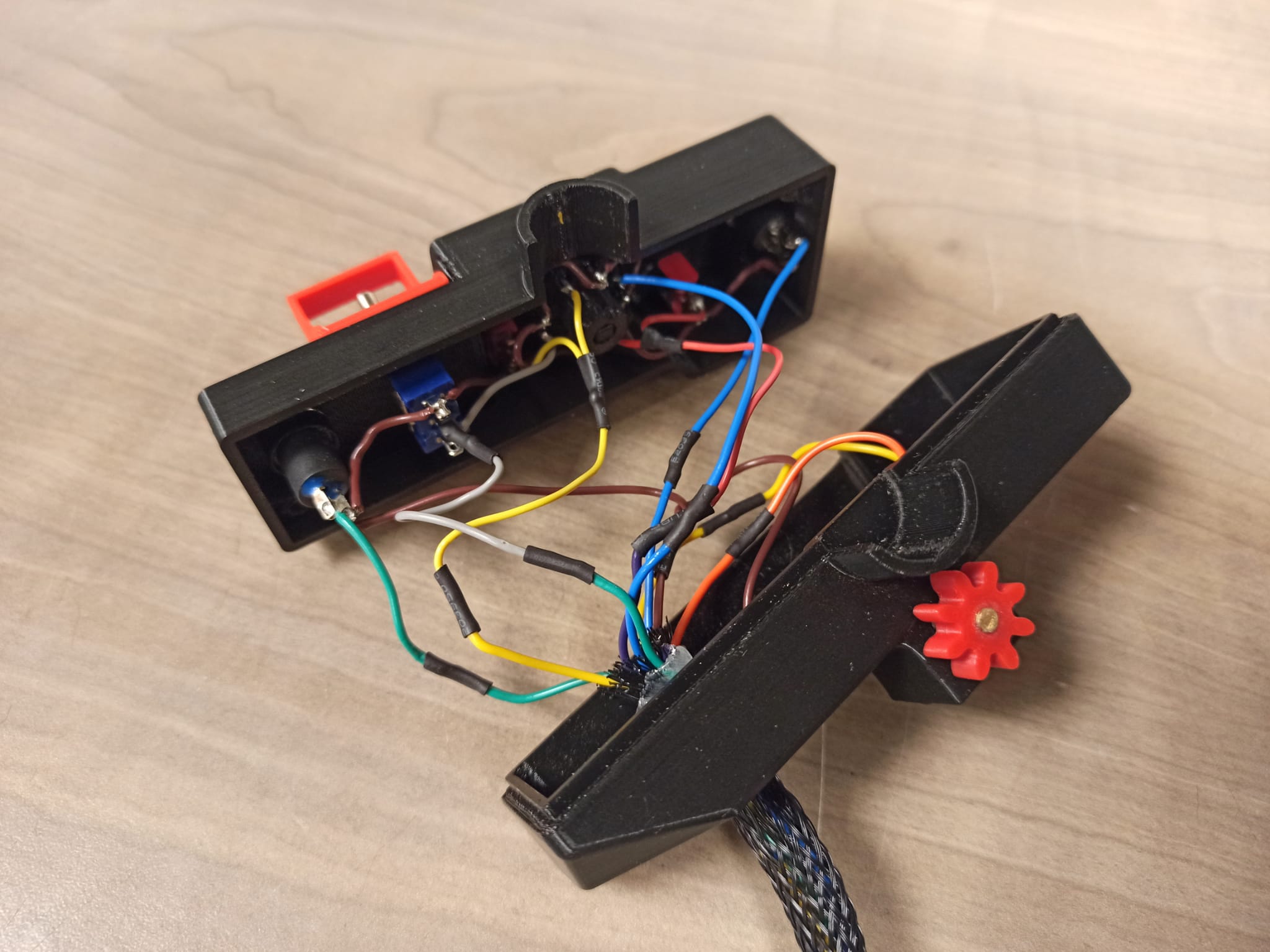
Base and Sensors
The matrix rows and columns can be soldered to a DB15 connector itself leading to a wire loom down to the base.
Here an enclosure contains the microcontroller, connected to two Hall effect sensors in the same way as the rudder pedals.
In the case of the joystick, the full range of motion equates to a much smaller angle than the pedals.
In order to maintain full resolution on each axis, pie-slices with embedded magnets expose the sensor to the full pole to pole magnetic field.
To adjust the sensor reading at the center, these slices can be rotated up or down to compensate any offset in either the sensor or ADC.
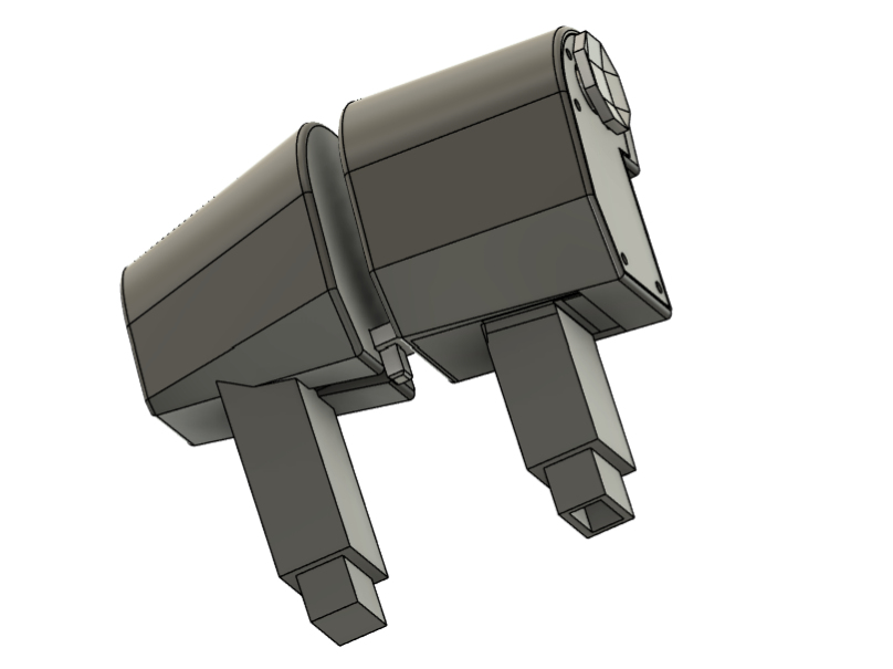
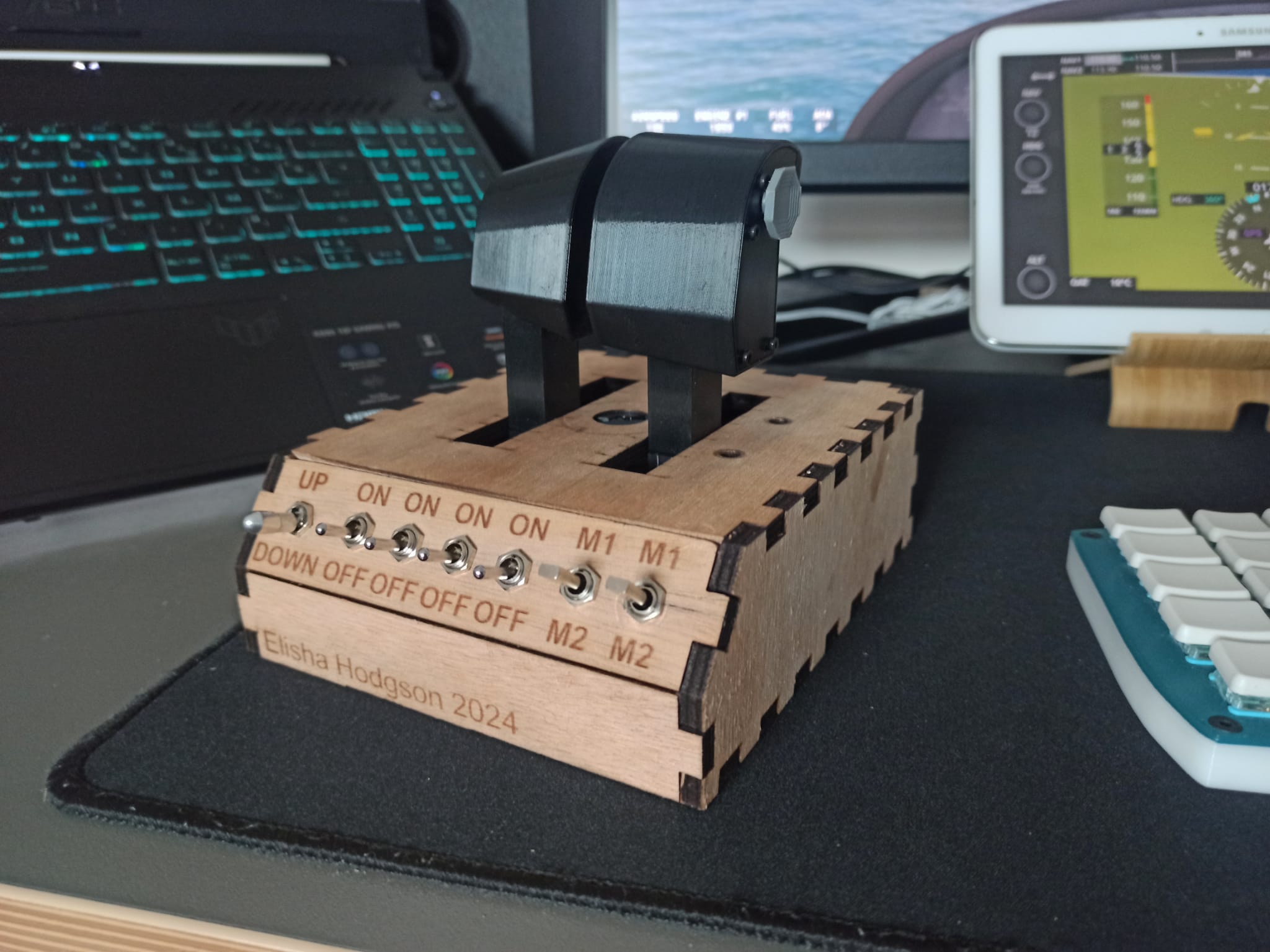
Throttle/Collective
Base
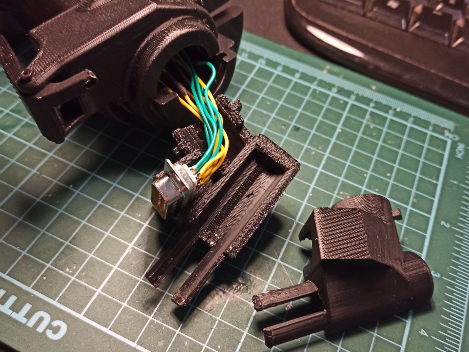
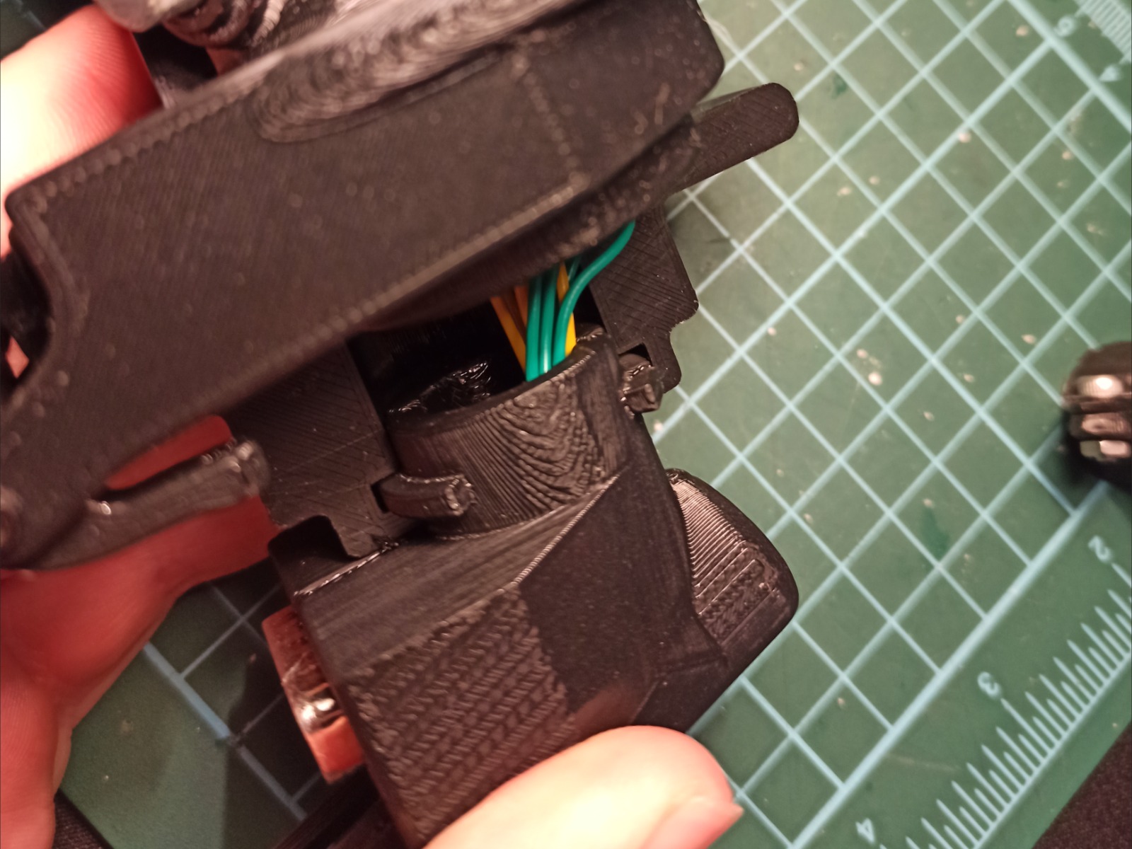
The throttle that also doubles as a collective has a couple of innovative features I have yet to see elsewhere.
Both sets of controls share the same base which can accommodate different add-ons depending on the use case.
Everything sits on a 3D printed spacer/frame encapsulated in a laser-cut enclosure.
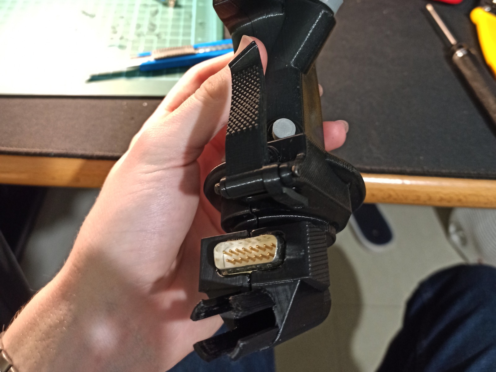
The two throttle levers fit onto carriages riding on a set of bearings riding on rails. The rail profile contains subtle sets of protrusions to haptically indicate 25%, 50% and 75% throttle. The carriages are linked to the sliders of two linear potentiometers outputting an analog signal to a DAC on the microcontroller. The right side is hollowed out to allow for the wires leading to a 4-way hat and 2 extra buttons. After struggling to find a 7 pin connector that fitted my form factor, I glued a set of Dupont connectors together resulting in an asymmetrical connector that can't be plugged in incorrectly and with flawless performance so far.
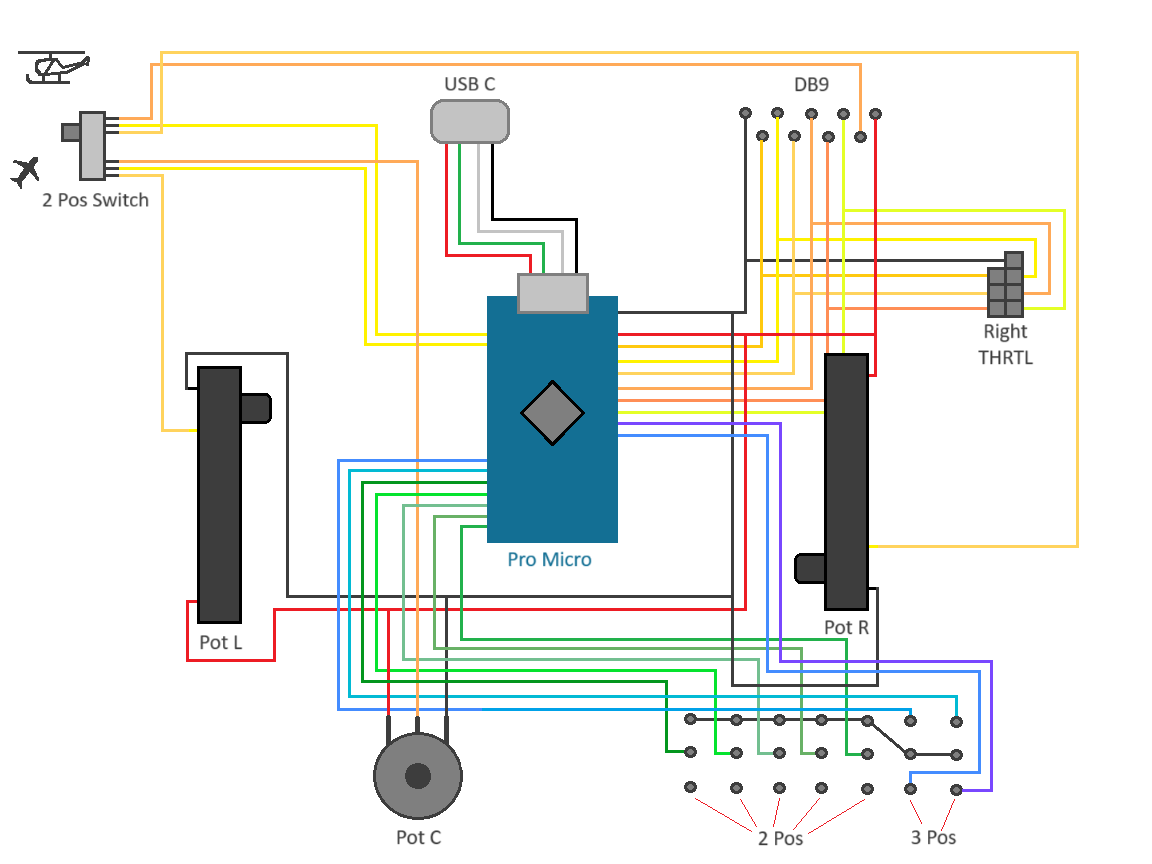
The 2 position switch on the back of the case tells the base which configuration is in use. The wiring diagram reveals that all it's doing is physically connecting either the linear potentiometers from the throttle to the MCU, or the rotary potentiometers of the collective/twist grip throttle. This is only necessary because there aren't enough GPIO on the MCU for everything to be connected at the same time.
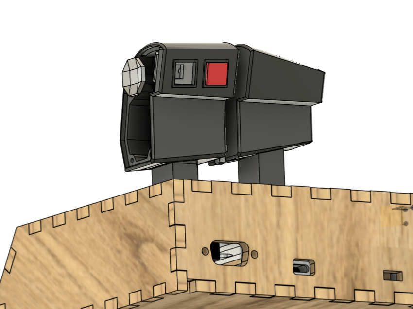
The DB9 connector at the top is where the collective lever plugs in to the base unit, it can be seen as the equivalent to the 7-pin Dupont connector for the throttle, but with an additional 5V and signal wire for the throttle potentiometer.
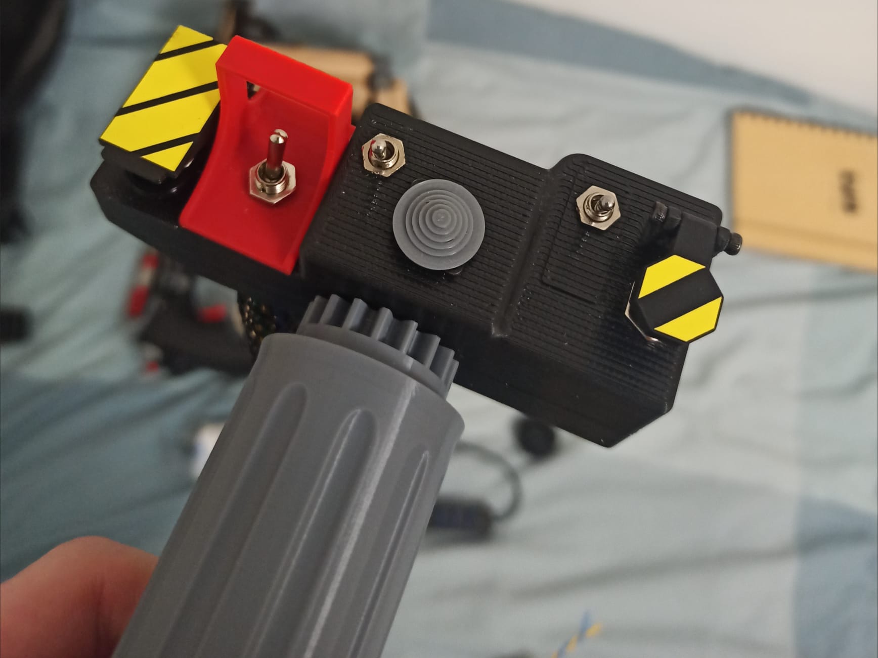
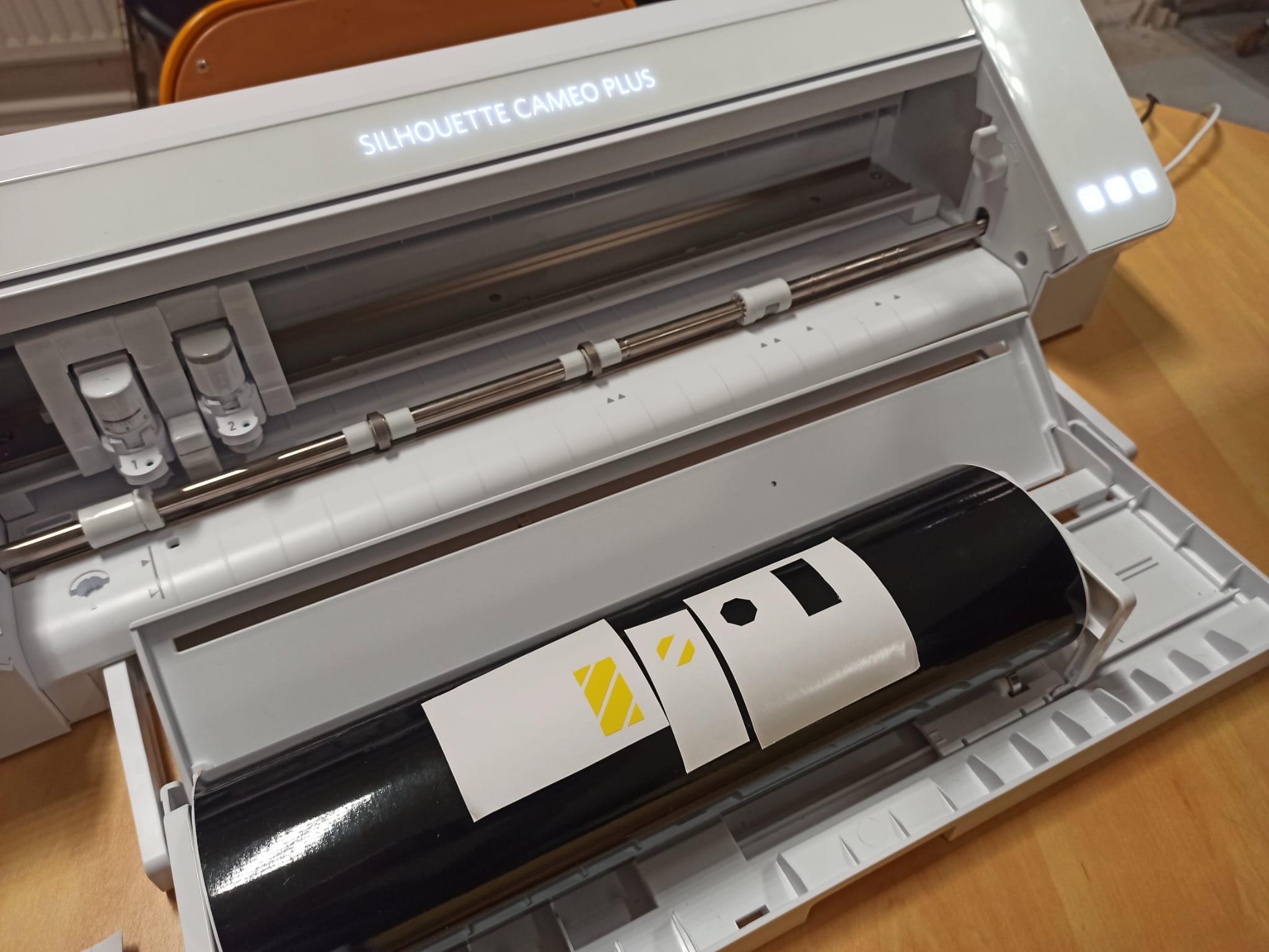
The grip is modelled after the H125 collective, contains a twist grip throttle, and can be finished off with vinyl stickers on the switch caps for an accurate appearance.
Instead I wrote a fairly simple Arduino script using the USB joystick library.
This works fine but wouldn't have been feasible for all three MCUs in his project. The Arduino framework doesn't grant access to the configuration of the USB Vendor ID which is necessary for the PC to be able to tell the three peripherals apart.
This would result in the button on a certain GPIO of one peripheral overwriting the state of the button on the other peripheral's equivalent GPIO.
MM-Joy2 allows the VID to be edited, so as long as 2 of the 3 Pro Micros have custom VIDs, no overwriting occurs.
Everything sits on a 3D printed spacer/frame encapsulated in a laser-cut enclosure.
The two throttle levers fit onto carriages riding on a set of bearings riding on rails. The rail profile contains subtle sets of protrusions to haptically indicate 25%, 50% and 75% throttle. The carriages are linked to the sliders of two linear potentiometers outputting an analog signal to a DAC on the microcontroller. The right side is hollowed out to allow for the wires leading to a 4-way hat and 2 extra buttons. After struggling to find a 7 pin connector that fitted my form factor, I glued a set of Dupont connectors together resulting in an asymmetrical connector that can't be plugged in incorrectly and with flawless performance so far.
The 2 position switch on the back of the case tells the base which configuration is in use. The wiring diagram reveals that all it's doing is physically connecting either the linear potentiometers from the throttle to the MCU, or the rotary potentiometers of the collective/twist grip throttle. This is only necessary because there aren't enough GPIO on the MCU for everything to be connected at the same time.
Throttle Levers
I modelled the throttle levers after that of the A10 Warthog throttle, then added as many switches as I had GPIOs left for without making another matrix.
Instead each switch pulls its own GPIO to ground.
The hat uses the same internal parts from the F16 grip, and the two other buttons use more of the same 4mm switches held within the 3D printed levers.
The left lever is smaller and doesn't contain any electronics since I'm using it with my left hand (so my thumb, index and middle finger only rest on the right lever).
The left lever instead holds a switch that can be slid out into a hole on the right lever, securing both levers together for single engine planes.
Collective Lever
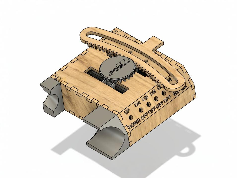
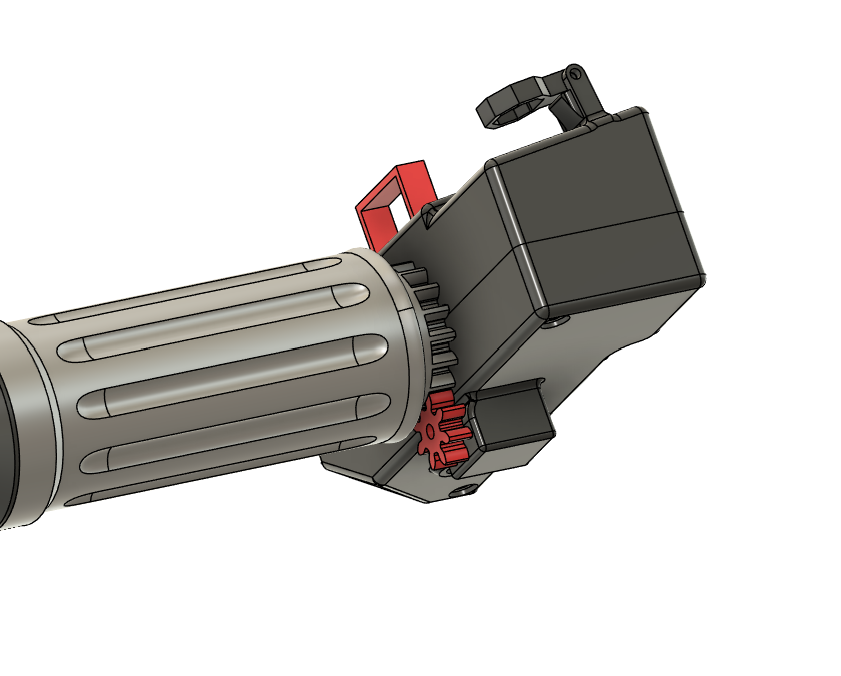
In rotorcraft configuration, the collective base is mounted sideways to a chair, and the throttle levers are replaced by a magnetic spur gear and screw-on arched track.
This design is extra compact as the collective perceived pivot point is shifted back by 20cm, shortening the lever whilst maintaining the same trajectory as a 45cm lever.
The DB9 connector at the top is where the collective lever plugs in to the base unit, it can be seen as the equivalent to the 7-pin Dupont connector for the throttle, but with an additional 5V and signal wire for the throttle potentiometer.
The grip is modelled after the H125 collective, contains a twist grip throttle, and can be finished off with vinyl stickers on the switch caps for an accurate appearance.
Throttle/Collective Firmware
Unlike the joystick and pedals assemblies, the throttle/collective can't run MM-Joy2 since the method of wiring the switches used isn't supported.
Instead I wrote a fairly simple Arduino script using the USB joystick library.
This works fine but wouldn't have been feasible for all three MCUs in his project. The Arduino framework doesn't grant access to the configuration of the USB Vendor ID which is necessary for the PC to be able to tell the three peripherals apart.
This would result in the button on a certain GPIO of one peripheral overwriting the state of the button on the other peripheral's equivalent GPIO.
MM-Joy2 allows the VID to be edited, so as long as 2 of the 3 Pro Micros have custom VIDs, no overwriting occurs.
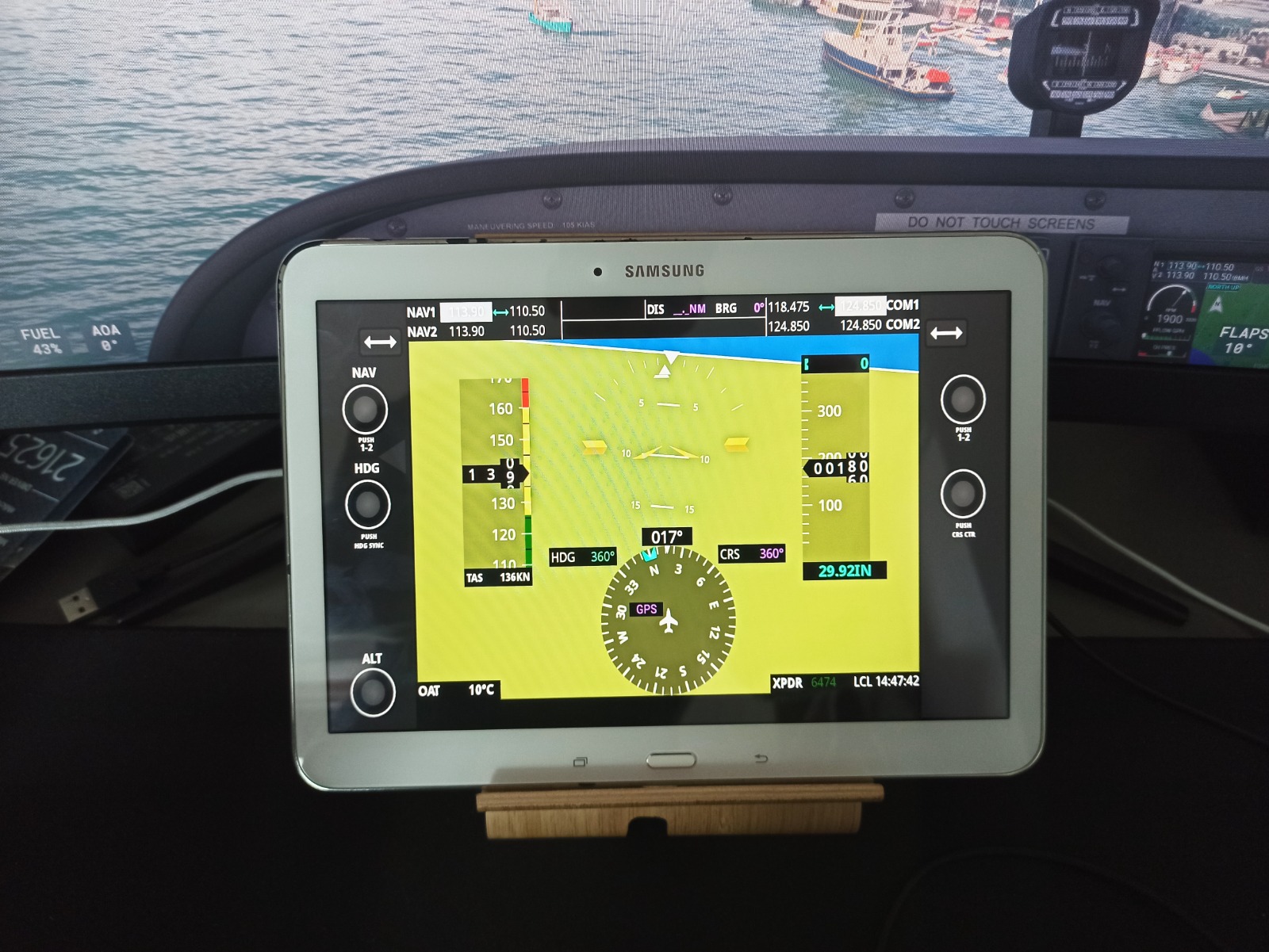
Primary Flight Display
Old Tablet, New Purpose
The Samsung Galaxy Tab 4 SM-T530 was released in 2014. Its final Android update was 5.0.2 Lollipop which hasn't been supported by the Playstore for years.
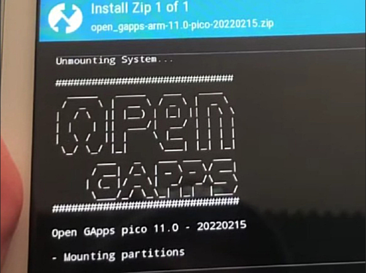
Thankfully this model can be rooted, which is exactly what I did using LineageOS via recovery, now running Android 11 and supporting the Google Apps once again.
This means we can use one of the many apps for building customisable displays, reading telemetry data from MSFS24 over either USB or WIFI. In the photos here I'm currently using a layout designed to recreate the Garmin G1000.
I was so impressed with the speed boost resulting from the removal of the build up, I replaced the battery, restoring the device to a perfectly usable media/web-browsing tablet.
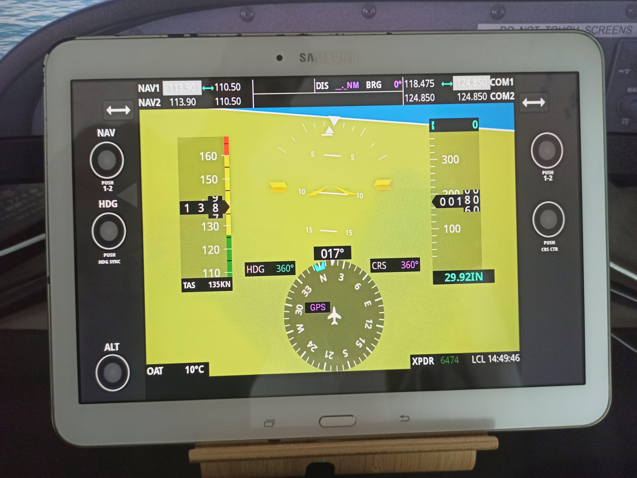
Firmware Flashing Screenshots from channel48 on YouTube
Final Thoughts
I'm very happy with this project, both in the finished product and some of the topics explored on the way (new tools in CAD, custom OS flashing, ...)
Each of the requirements were met:
The box fits perfectly on a shelf
No corners were cut in the function and feel of the sim controls.
Though I already had some of the bearings, plywood and filament, the cost of everything else comes to around 35-40%.
That's at least 10 times cheaper than any other similar commercially available offerings.
If I were to revisit any aspects of the project one day, I would like to make the collective mechanism more robust as the 5mm thick plywood has more flex in some places than I would like. Other than that I don't really have any complaints and am very pleased with the sim rig.
Each of the requirements were met:
If I were to revisit any aspects of the project one day, I would like to make the collective mechanism more robust as the 5mm thick plywood has more flex in some places than I would like. Other than that I don't really have any complaints and am very pleased with the sim rig.
Thank you for reading this far.
If you would like any information, diagrams, CAD or code feel free to ask. I wish you the same satisfaction of making something you're proud of, and that your curiosity may lead you down exciting paths resulting in cool projects.
If you would like any information, diagrams, CAD or code feel free to ask. I wish you the same satisfaction of making something you're proud of, and that your curiosity may lead you down exciting paths resulting in cool projects.